Thermodynamic analysis of the C-13-1 steam catapult for aircraft launching from an aircraft carrier
Análisis termodinámico de la catapulta de vapor C-13-1 para lanzamiento de aeronaves desde un portaviones
José García Cascallana (1)
Abstract
This manuscript presents a thermodynamic analysis of thermal energy storage regarding C-13-1 catapult used to launch aircraft from the USS Nimitz CVN-68. The results showed a steam injection coefficient of 4.4%. In this way, the simulated accumulator reduces steam thermal power supplied in batch mode from 530 MW required for launch to 22.9 MW, provided continuously by the generator throughout the whole cycle. The total thermal energy consumed was 1389 MJ. The forces exerted during take off an FA-18 Hornet indicated 85.9% action for the catapult and 14.1% for the turbofans, with 1.9% corresponding to friction forces on the total traction.
Keywords: Flash steam, steam accumulator, thermal energy storage, steam generator, batch process.
Resumen
En este artículo se realizó el análisis termodinámico de la acumulación de vapor para almacenamiento de energía térmica. El sistema analizado fue la catapulta C-13-1 utilizada para el lanzamiento de aeronaves desde el USS Nimitz CVN-68. Los resultados mostraron un coeficiente de inyección de vapor de 4,4%. De esta forma, el acumulador simulado reduce la potencia térmica del vapor suministrado a la catapulta desde los 530 MW necesarios en forma batch por lanzamiento a 22,9 MW aportados por el generador de forma continua en todo el ciclo; la energía térmica consumida son 1.389 MJ. Las fuerzas ejercidas durante el despegue de un FA-18 Hornet indicaron el 85,9% de acción para la catapulta y el 14,1% para los turbofan, de los cuales el 1,9% correpondían a las fuerzas de fricción sobre la tracción total.
Palabras clave: Vapor flash, acumulador de vapor, almacenamiento de energía térmica, generador de vapor, proceso por lotes.
Recibido/ received: 03/05/2023 Aceptado/ accepted: 20/06/2023
(1) Ingeniero Técnico Industrial por la Universidad de León, Ingeniero Industrial por la Universidad Nacional de Educación a Distancia (UNED) y Doctor por la Universidad de León (España, Spain).
E-mail: jg*****@***oo.es
1. Introduction
Steam accumulators are used as thermal energy storage to balance steam fluctuations between supply and consumption. These systems considerably improve the operating conditions and quality of the steam supplied, saving thermal energy. However, steam accumulators are difficult to implement due to the high initial investment costs required, as they depend mainly on the volume and pressure needed (Sung et al., 2016). Batch processes are a typical example of this type of situation, where a huge amount of steam is required for short periods. Steam generators cannot react instantaneously to steep modifications in demand (Biglia et al., 2017).
A steam accumulator saves energy, reduces pressure fluctuations and the aging of pressurised lines and vessels in steam generator. There are two thermodynamic models for calculating steam accumulator units: equilibrium and non-equilibrium models. The first one is based on equilibrium equations associated with the global mass and energy balance of water and steam content in the tank. The second one uses mass and energy equations for each phase and establishes non-equilibrium evaporation and condensation rates. The dynamic changes in steam consumption cause pressure changes in pipes and pressurised vessels, originating dynamic thermomechanical loads that endanger equipment integrity. These adverse effects are reduced when steam accumulators are installed (Stevanovic et al., 2015).
The energy efficiency of a steam generator decreases rapidly with increasing the fluctuation frequency of the consumer steam load. This efficiency is increased by 3-11% when a steam accumulator is installed (Jiacong, 2000). The charging process constitutes the supply of saturated or superheated steam from the steam generator to the steam accumulator. The unloading causes a pressure reduction of the saturated water while releasing flash steam (Yang et al., 2017). An example includes the use of steam for applications in which work is carried out for a short period, such as steam catapults for launching aircraft or in power plants during peak loads (Stevanovic et al., 2012). Beside steam accumulators, other technologies commercially available for thermal energy storage include the two tank of molten salts with application in concentrated solar power plants (González-Roubaud et al., 2017). Direct storage of saturated or superheated steam in pressure vessels is not economical due to its low energy density. Water is the preferred storage medium below 100 °C because of the high specific heat value, great availability, environmental safety and low cost (Stark et al., 2017). The steam accumulator is an essential part of the steam catapult of an aircraft carrier, as it provides the necessary amount and pressure of saturated steam in an extremely short time, ensuring that the aircraft acquires the take off speed within the short deck length. The fact that the steam catapult system propels an aircraft of more than 20 t at take off speeds of more than 200 km/h in about 2 s, gives an idea of the strong imbalance the accumulator is submitted (Sun et al., 2015).
Hydraulic catapults gave way to steam catapults in the 1950s, while in the early 2000s, an alternative technology for launching aircraft was developed, called the electromagnetic catapult, which is powered by linear induction motors working on the same basic principles as electric induction motors. The United States Navy developed the electromagnetic aircraft launch system (EMALS) which was installed on the USS Gerald R. Ford (CVN-78) aircraft carrier, the first of a new generation (Parwate et al., 2017). However, this new technology has a high cost compared with the steam catapult system.
Objetive
This manuscript aimed to analyze thermal energy storage by a steam accumulator using high pressure saturated water to supply steam to a C-13-1 catapult for launching aircraft from the CVN-68 aircraft carrier deck. The kinematics and dynamics of the entire aircraft launching system and the mass and energy balance of the steam system at the operating point were studied. This study allows understanding the interaction between forces developed by the catapult and turbofan for different aircraft take off scenarios.
2. Materials and methods
2.1. Description of the scenario
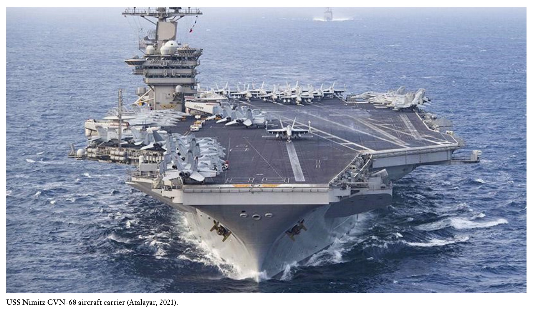
The C-13-1 steam catapult currently installed on the CVN-68 aircraft carrier (first in the series) consist of two rows of slotted cylinders inserted into a channel 1.07m deep and 1.42 m wide located directly below the fly deck (Zhou & Huang, 2020). The main characteristics of the CVN-68 are: displacement 101000 t, length 328.3 m, width 76.8 m, draught 11.3 m, 2 nuclear reactors A4W (aircraft, fourth generation, Westinghouse) of 104MW, 4steam turbines and 4 propellers, cruise speed 56 km/h, crew 3200 people, 82 aircraft, 4 lifts and 4 steam catapult C-13-1 (F16, 2020). Table 1 presents the main data for three steam catapults, along with the aircraft carriers, aircraft take off speed, aircraft maximum operational weight, among others.
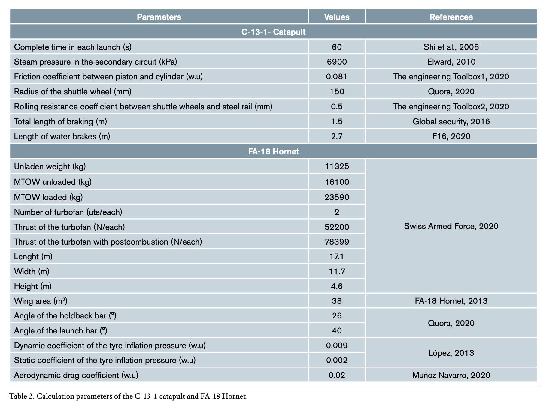
MTOW, take off speed and cycle time constitute the “operating point” of the C-13-1 catapult for the calculation. All other parameters of the C-13-1 steam catapult and main characteristics of the FA-18 Hornet were based on data shown in Table 2.

 2.2. Description of the operation of the C-13-1 steam catapult
The operating system mainly consists of: (1) steam supply from the secondary circuit of nuclear reactor, (2) inlet valve, (3) steam accumulator, (4) launch valve, (5) cylinders and pistons, (6) water brakes, (7) cylinder preheating system, (8) firefighting system, (9) drainage line, (10) retraction system, (11) cylinders lubrication system, (12) deck control cabin and (13) jet blast deflector (JBD).
The pressurized saturated water primary circuit of the two A4W reactors, pressurized water reactors (PWR) and UO2 fuel, transfers the thermal energy to the steam generator (secondary circuit). Water from the condenser in this circuit changes to saturated steam. The system operates as a Rankine cycle. The four propellers, electrical generators, auxiliary services and four catapults of the aircraft carrier are driven by the energy of steam.
The accumulator contains saturated water at the same pressure and temperature as the inlet steam. An instantaneous pressure change occurs when the outlet accumulator steam valve opens (launch valve). Flash steam is generated at lower pressure and temperature, and it is sent to the two cylinders of the catapult. Steam expansion in the cylinders activates the two pistons transmitting movement to a mechanism called the launch bar, to which the aircraft is attached by the front landing gear. Thus, take off speed is achieved in a short time, combining the catapult traction force and turbofan full load thrust, operating without post-combustion.
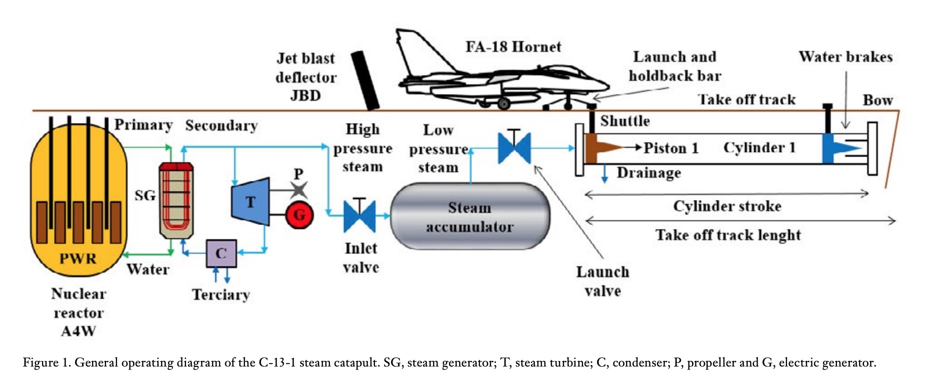 The cylinder preheating system allows valves, pipes, cylinders, pistons and all elements between the accumulator and the catapult to be slowly preheated to increase temperature to values close to operating conditions (Global security, 2020). Water brakes slow piston speed to a complete stop at the end of the cylinder stroke, dissipating their kinetic energy against the water and the deck structure. The retraction system allows pistons to return to their initial position when the launch is finished and the steam used is sent to the drainage steam line by opening the exhaust valve. The lubrication system reduces friction between cylinders and pistons. The JBD protects the operators and other aircrafts against the turbofan exhaust gases and it forms a 50° angle with the horizontal in order to deflect it to the atmosphere (SBIR-STTR, 2019). Figure 1 shows the general operating diagram of the C-13-1 steam catapult.
 Each catapult has two rows of launching cylinders mounted in parallel in the deck channel. The cylinder cover acts as a clamp that holds the slotted part of the cylinder in position to prevent radial scattering when applying steam pressure. Figure 2a shows the cross section and Figure 2b the longitudinal section of the catapult launch system.
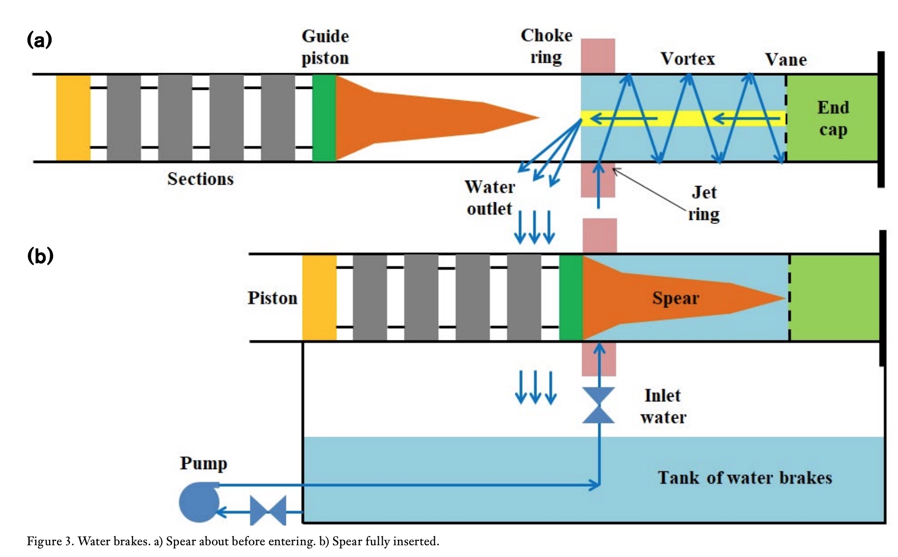
Figure 3a represents when the piston approaches the water brake at take off speed. The brakes are always full of water before the impact. This is done by continuously injecting water under pressure into the jet ring, giving a vortex movement to the jet so that it moves helically along the walls of the brake towards the rear, leaving a space in the center with only air. When the water reaches the vane of the brake end cap, the vortex is broken and water flows through the central part of the brake in the opposite direction, displacing the air and flowing towards the water tank in an existing opening next to the choke ring, constituting a closed water circuit. Figure 3b shows the piston stopping moment with the spear fully inserted into the brake and water flowing out completely from the duct next to the choke ring into the water tank. Once the piston is retired, a pump introduces water again into the jet ring to keep the brake full of water in a continuous movement until the next release (Garstin, 2016).
A complete launch cycle consists of: (1) approach of the aircraft to the launch site, (2) lifting of JBD, (3) launch and holdback bar coupling, (4) setting of the turbofan power to the maximum without post-combustion, (5) launch, (6) braking and (7), retraction of pistons to the launch site, extraction of excess steam, filling of water brakes and lowering of JBD (Navy BMR, 2020).
 2.3 Description of equations
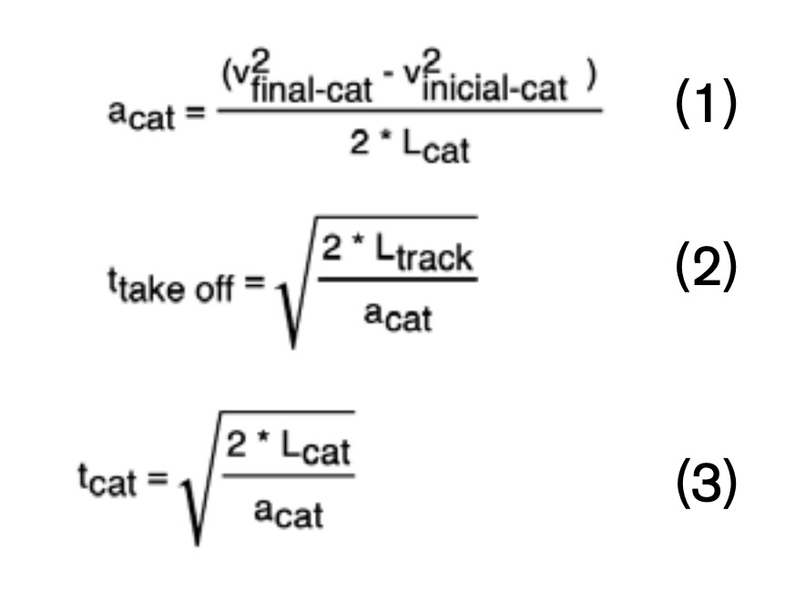
Equation 1 allows calculating shuttle and aircraft acceleration without considering any friction. Equations 2 and 3 estimate the take off and catapult operating time, assuming as a simplification that acceleration remains constant from the end of the catapult (94.2 m) to the runway (99.0 m), although in this small section of the track, the aircraft is only operated by the two turbofans.
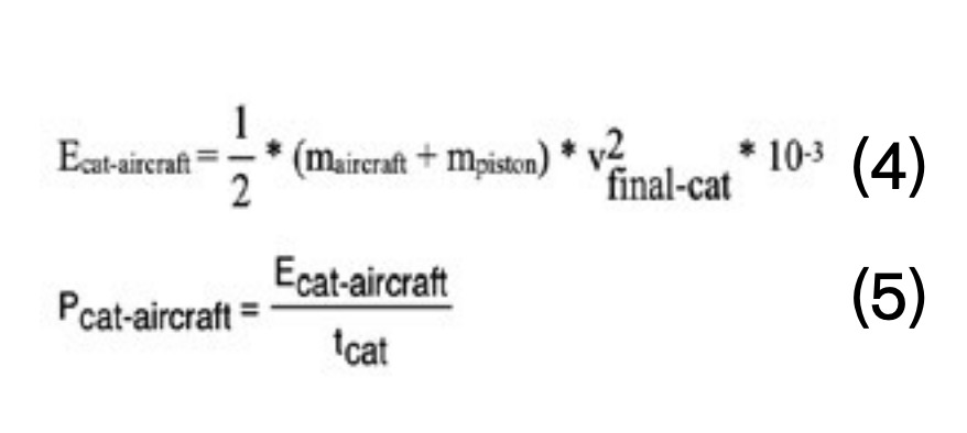
 Equation 4 is used for estimating the energy imparted by the catapult to allow aircraft take off, while Equation 5 calculates the power associated.
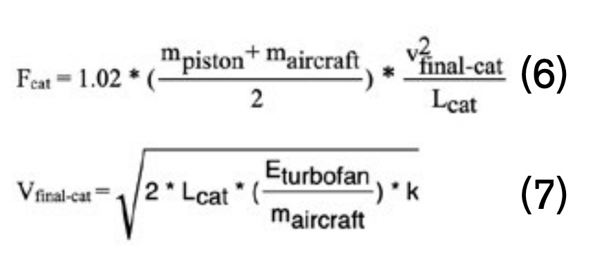
 Equation 6 calculates the traction force required for the catapult and associated with the expansion of steam into the cylinders. Equation 7 calculates the speed reached by the airplane when driven by turbofans (k = 0.8), considering in both cases the friction associated with the launch system and the aircraft (Hernando-Díaz, 2018).
 Equation 8 expresses the negative braking acceleration of the pistons obtained after their complete stop in the water brakes. Equation 9 the braking time, which is the time needed for pistons to stop. Equation 10 the exerted force of the catapult shuttle. Equation 11 the braking energy of the pistons and Equation 12 the average braking power dissipated in the water brakes of cylinders.

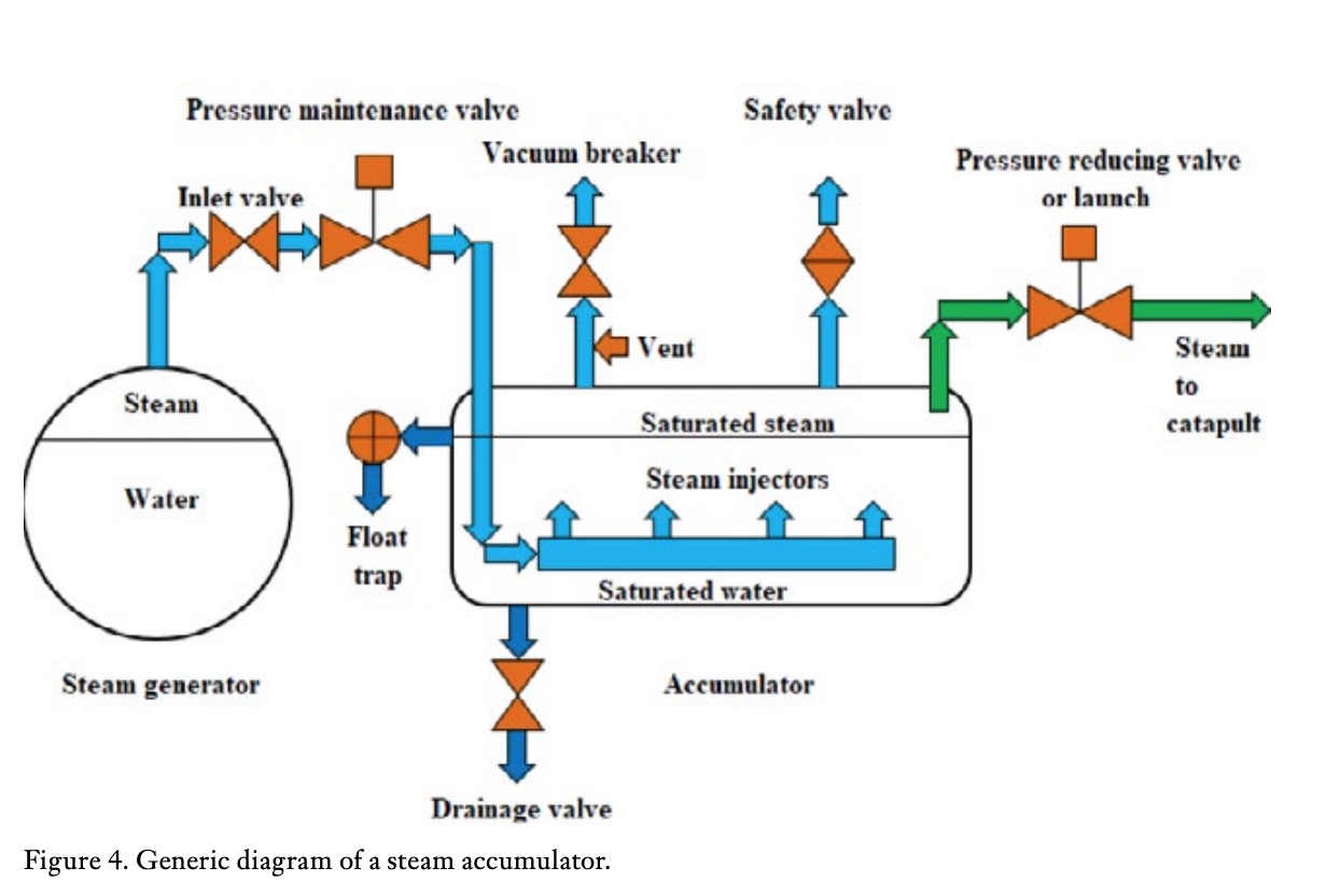 Garstin (2016) considers that steam expansion in the cylinders is not adiabatic for the whole piston stroke. However, Shi et al. (2018) assume adiabatic expansion. When assuming the ideal pressure value, the pressure starts from zero, rises almost linearly until it reaches its nominal value at the point corresponding to 10% of the cylinder stroke position and then remains constant for the remaining 90% of the stroke. On the contrary, when assuming real pressure values, only when reaching 43% of the stroke position and up to the end, the actual expansion resembles an adiabatic process (Garstin, 2016). For simplification, steam was assumed to expand ideally from the beginning to the end, in an isobaric way inside the cylinders. The thermodynamic model was the equilibrium model. Figure 4 shows a generic diagram of a steam accumulator (Spiraxsarco, 2017).
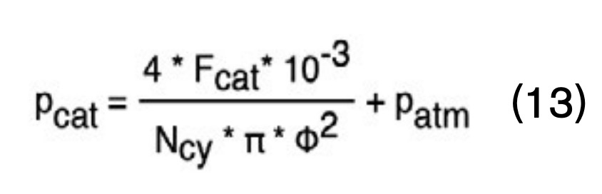
Equation 13 estimates the accumulator absolute steam pressure required for aircraft launching, in accordance with C-13-1 catapult design parameters, considering that atmospheric pressure opposes movement. Although the launch steam pressure can vary between certain values (3061-3537 kPa, Roosvelt aircraft carrier, CVN-71) (EPA, 1999), in this work it was considered constant and estimated as a function of the operating point.
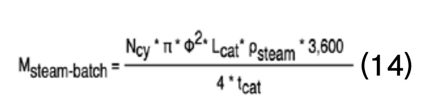
 The steam mass flow required for a launch is calculated using Equation 14.
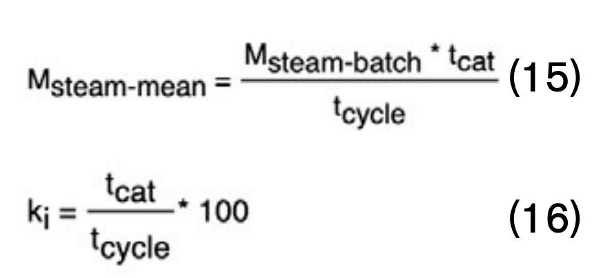
 Equation 15 estimates mean steam consumption. This value is coincident with the steam mass flow from the steam generator in a continuous manner. Equation 16 is used to obtain the steam mass flow based on the steam injection coefficient.
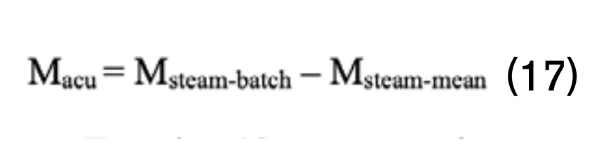
 The thermodynamic model adopted for evaluating the steam accumulator was based on equilibrium. The steam mass flow delivered to the catapult is supplied by the steam generator operating continuously. The steam accumulator only works during the steam injection phase (batch conditions). Equation 17 represents the mass flow of flash steam produced by the accumulator as the difference between the steam supplied in each batch and the mean steam value (as mass flow).
 Equation 18 represents the amount of saturated water stored in the steam accumulator needed to supply steam to the catapult. Equation 19 represents the amount of flash steam sent to the catapult and expressed as percentage.

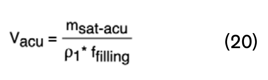 Equation 20 is used to calculate the volume of the accumulator considering a filling factor of 0.9 (Wenqiang et al., 2017). Dimensions of the cylindrical tank were calculated with a length/diameter ratio of 5 (Stevanovic et al., 2012).
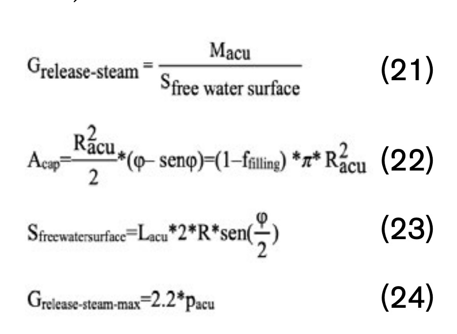 Equation 21 gives the degree of steam released from the accumulator. Equation 22 the area of the cylinder cap obtained after applying the filling factor. Equation 23 the water free surface area and Equation 24 the maximum value of steam release degree (Spiraxsarco, 2017).
Figure 5a shows in a simplified way, forces considered during the launch of the FA-18 Hornet aircraft from a C-13-1 catapult. It was assumed that all forces act on point O (without considering moments) where the shuttle is attached to the launch bar. Figure 5b shows the force diagram, acting on the shuttle, where point O is located close to the deck.
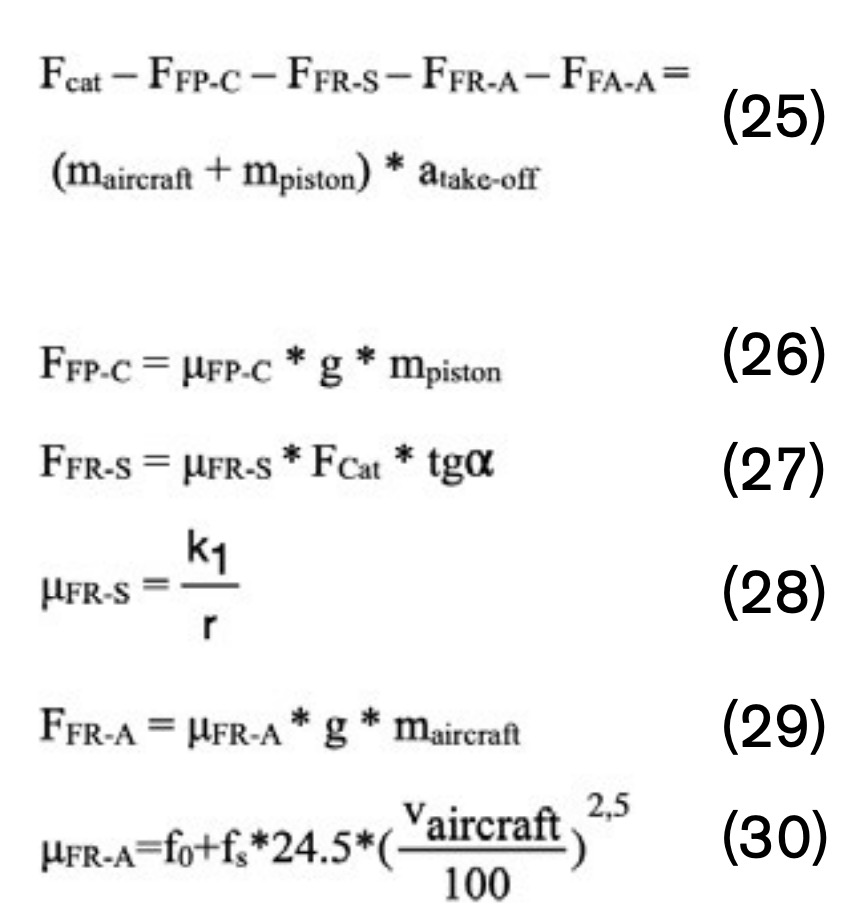 Equation 25 represents the “launch equation” for the FA-18 Hornet. Equation 26 is used to calculate the friction force between pistons and cylinders. Equation 27 and 28 are used to calculate the friction force and coefficient associated with the shuttle wheels, whereas Equation 29 and 30 for estimating friction for the aircraft wheels (López, 2013).
Equation 31 calculates the aircraft aerodynamic friction force, using in this case the aircraft speed in m/s as units.


 3. Results and discussion
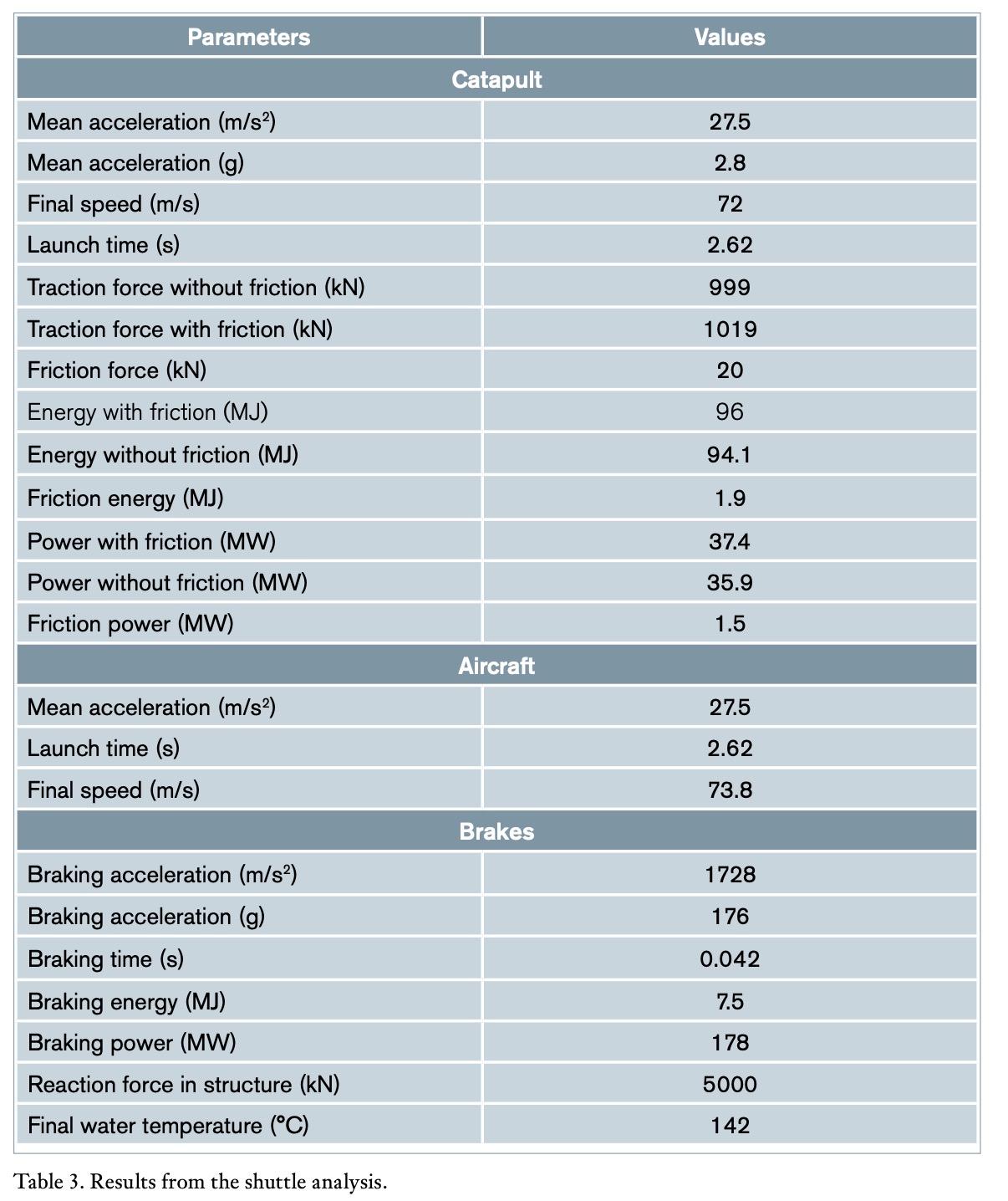
3.1. Shuttle analysis
Table 3 shows results from the analysis of elements coupled to the shuttle: catapult, aircraft take off and piston braking. The catapult nominal launch capacity (36288 kg) was divided into the aircraft mass to be launched (33408 kg) and shuttle-piston mass (2880 kg). The aircraft acceleration from the point of shuttle release (94.2 m) and the runway end (99.0 m) was assumed constant, even though only the turbofan thrust acts on this section (3.8 m). The difference in speed and final time between catapult and aircraft take off is only 2.4%; this fully justifies the assumption for the catapult and take off parameter as equivalent at the operating point. The shuttle transmits a horizontal traction force to the aircraft of 1019 kN (when friction is considered). This force is supplied in 2.62 s by steam from the accumulator. A 2% loss was assumed in Equation 6. The negative acceleration exerted on pistons by water brakes has a value of 1728 m/s², generating a reaction on the deck fuselage equivalent to 5000 kN (510 t). This value corresponds to 0.5% of the aircraft carrier mass and raises the water temperature up to 142 °C.
 3.2. Steam system analysis
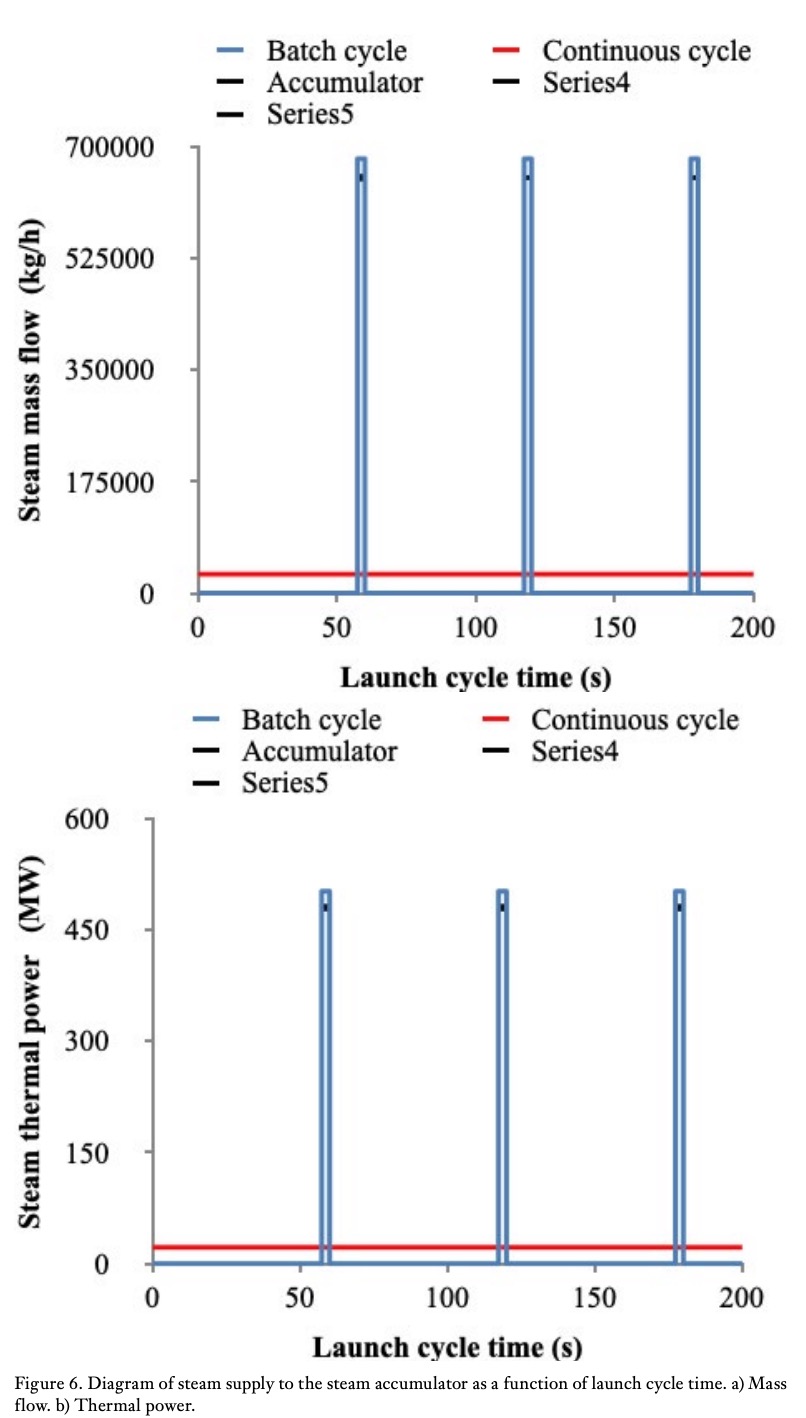
Figure 6a shows represents the flow of steam supplied by the accumulator to the catapult and Figure 6b, the steam thermal power. Figure 6a also represents the flow of steam supplied by the boiler for each operating cycle as a function of the launch time at the operating point. The catapult delivers a mass flow of 680923 kg/h of steam in just 2.62 s in a cyclic way of 60 s duration. The mean value of steam supplied to the catapult was 29734 kg/h. This flow is produced by the steam generator, resulting in an injection coefficient of 4.4%. This means that during 4.4% of the launch cycle time, steam is injected into the catapult, while in the remaining time, energy is continuously stored in the accumulator. The accumulator supplies 651189 kg/h (95.6%) of steam which, added to the 29734 kg/h (4.4%) from the steam generator, constitutes the total value of 680923 kg/h (100%) required by each catapult cycle.
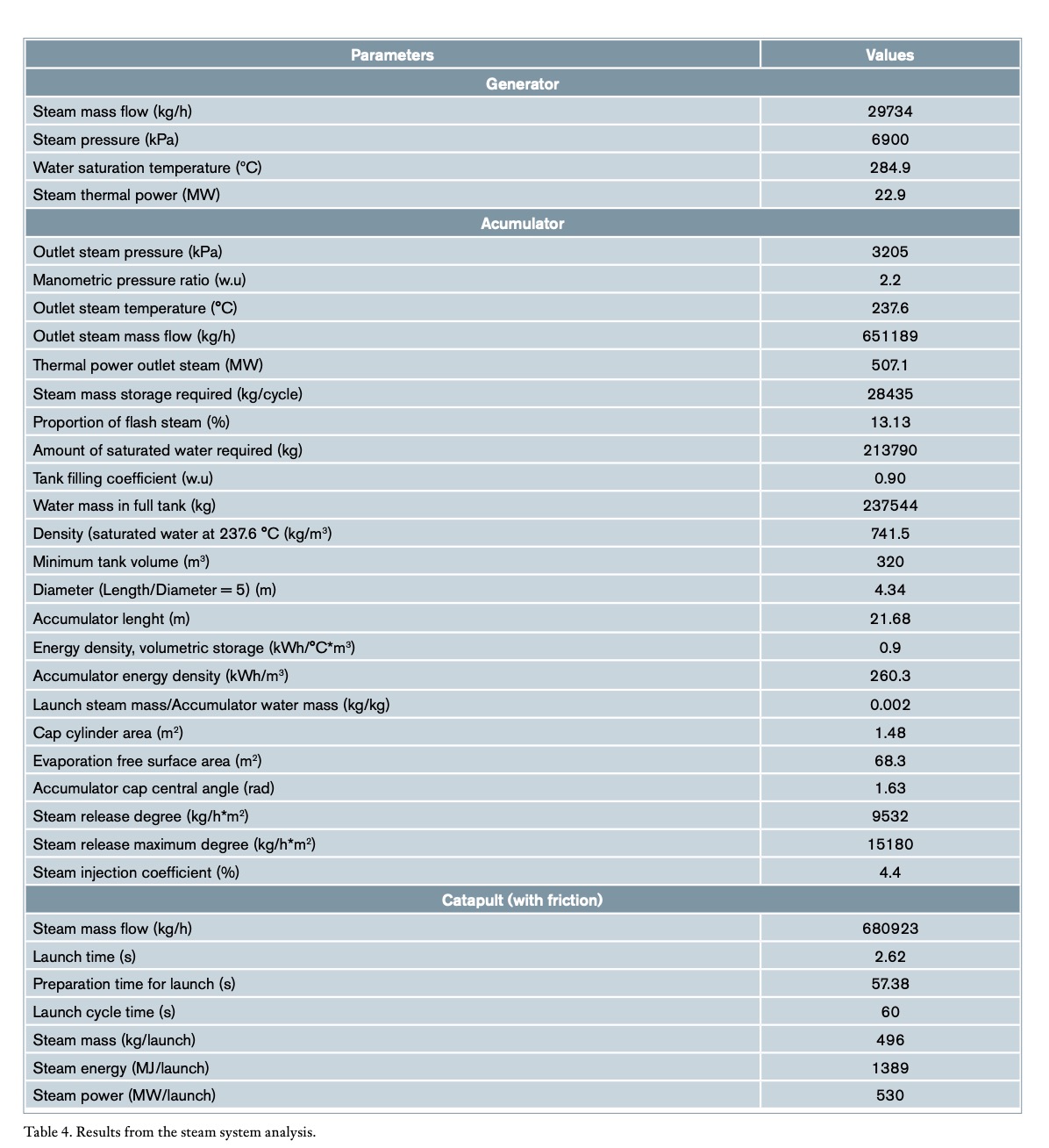
Results from the generator, accumulator and catapult are shown in Table 4. A horizontal configuration was assumed instead of a vertical one for obvious reasons of space in the aircraft carrier and because of the larger evaporation area provided by this configuration which depends on saturated free surface area in the tank.
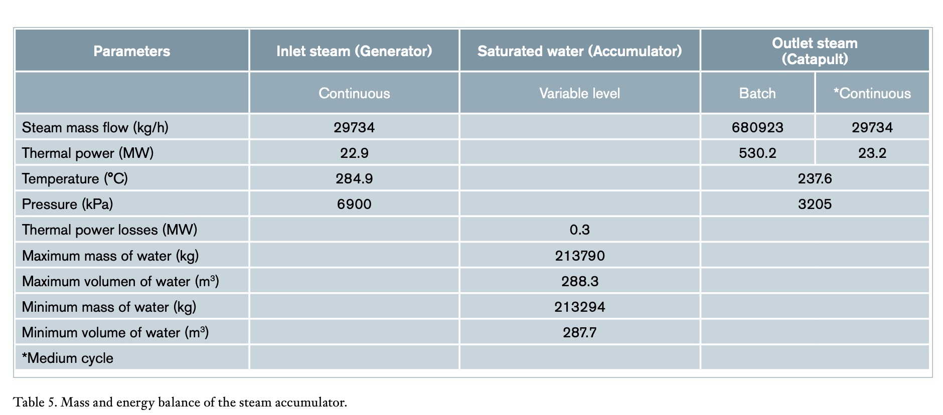
The steam accumulator, when filled to 90% of its total capacity, has a free evaporation area of 68.3 m² (3.15 m × 21.68 m) and a circular cap angle of 93.2°, resulting in a steam release rate of 9,532 kg/h*m². This value is lower than the maximum release rate of 15,180 kg/h*m² (Spiraxsarco, 2017). The ratio between high and low manometric pressures was 2.2:1. Table 5 presents the mass and energy balance of the steam accumulator for the complete cycle at the operating point (injection and non-injection). It is necessary to supply 0.3 MW additional to the energy provided by the accumulator to compensate the energy balance, due to the difference between the inlet specific enthalpy and outlet. This power of 0.3 MW represents just 1.3% of the total input thermal power, and therefore this amount was neglected.
 The steam accumulator, when filled to 90% of its total capacity, has a free evaporation area of 68.3 m² (3.15 m × 21.68 m) and a circular cap angle of 93.2°, resulting in a steam release rate of 9532 kg/h*m². This value is lower than the maximum release rate of 15180 kg/h*m² (Spiraxsarco, 2017). The ratio between high and low manometric pressures was 2.2:1. Table 5 presents the mass and energy balance of the steam accumulator for the complete cycle at the operating point (injection and non-injection). It is necessary to supply 0.3 MW additional to the energy provided by the accumulator to compensate the energy balance, due to the difference between the inlet specific enthalpy and outlet. This power of 0.3 MW represents just 1.3% of the total input thermal power, and therefore this amount was neglected.
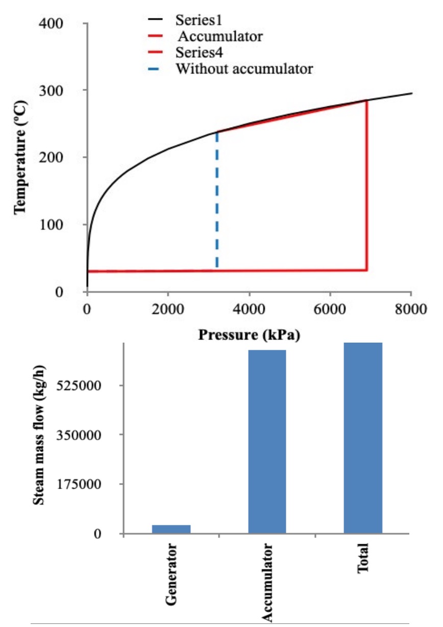
Figure 7a shows the temperature-pressure diagram of water-steam for the process in the accumulator and its comparison with the steam generator or boiler (operating without an accumulator) to achieve the same aim. The boiler is incapable of supplying the high steam flow needed in such a short time. Figure 7b compares the generator steam flow (4.4%) and that of the accumulator (95.6%) during each launch. Figure 7c and Figure 7d illustrate the process of batch and non-batch steam injection of the steam accumulator, while the steam supply from the steam generator is constant throughout the cycle.
 3.3. Analysis of the nominal traction capacity of the C-13-1 steam catapult
The effect of varying pressure and take off speed are analyzed. When Equation 6 is applied, a set of curves with a hyperbolic shape for each value of the traction force and steam pressure are obtained. Figures 8a and 8b show the evolution of the aircraft mass that can be launched as a function of the take off speed for each value of the catapult traction force and steam pressure in the accumulator. The black line in both figures indicates the nominal operating curve of the C-13-1 catapult and the red dotting arrow, the operating point. These curves were obtained by sealing off the thrust of the aircraft turbofans, only with the action of catapult.
 3.4. Analysis of an FA-18 Hornet take off
The take off of an FA-18 Hornet from an aircraft carrier or an airport with its MTOW has been analysed in a simplified way, assuming the effect of friction forces and also neglecting them. Equation 32 corresponds to the equation for the aircraft launch using only steam catapult and Equation 33 for turbofan, considering in both cases friction forces.
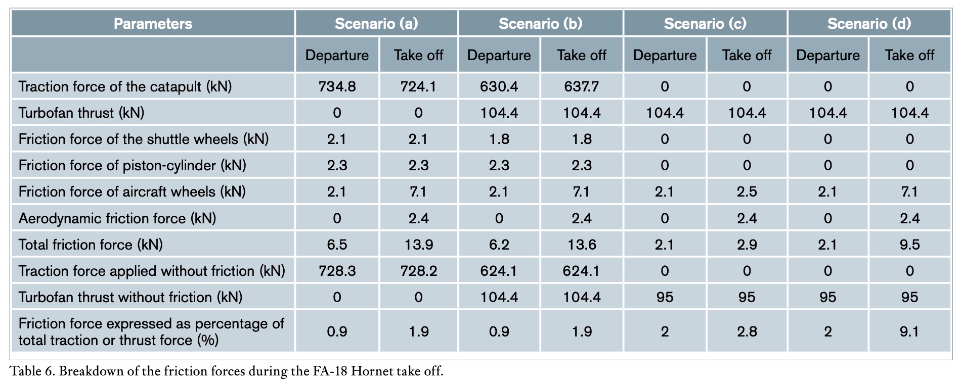
These equations clearly show that force (and therefore, acceleration) is variable and a function of the launch speed. However, the variation of acceleration is small, so the mean acceleration has always been considered. Table 6 shows each of the components of friction forces during the take off in accordance with four scenarios of the launch: (a) catapult, (b) catapult and turbofan, (c) turbofan in catapult track and (d) turbofan in airport track.
For Scenario (b), the following percentage of forces acting on the aircraft results: steam catapult 85.9% and turbofan 14.1%, approximately a 6/1 ratio. The results show the low incidence of friction, rolling and aerodynamic forces on the total force required for take off compared to that required to accelerate the aircraft-piston assembly. The results evidence the small incidence of friction, rolling and aerodynamic forces on the total force needed for launching compared with that required to accelerate the aircraft-piston assembly. The force required by the FA-18 Hornet for take off is 72.1% of the nominal catapult force when friction is neglected and 72.8% if considered. In this way, 98.1% of the catapult force is used to accelerate the aircraft-piston assembly and the remaining 1.9% is used to counteract the friction force that opposes the launch movement. Results are identical in the case of accelerating the aircraft with the catapult and turbofan providing the force. In the case of turbofan thrust and catapult track, the resulting friction force is 2.8%. When the take off takes place on the airport track, the friction force is raised to 9.1%, due to the increase of speed with respect to the previous case and with this value being much higher than that obtained for the launch using when the force provided by the catapult. The difference between the friction and frictionless force (or thrust) with zero speed is due to the term f0 of Equation 30. The resistance force caused by the air on the pistons was disregarded. Although the high piston speed causes a loss of air pressure when circulating through the cylinders. However, the air density is just 0.7 kg/m3 at 237.6 °C, thus the force resulting from the air opposing to the piston movement within cylinders is small and it was neglected.


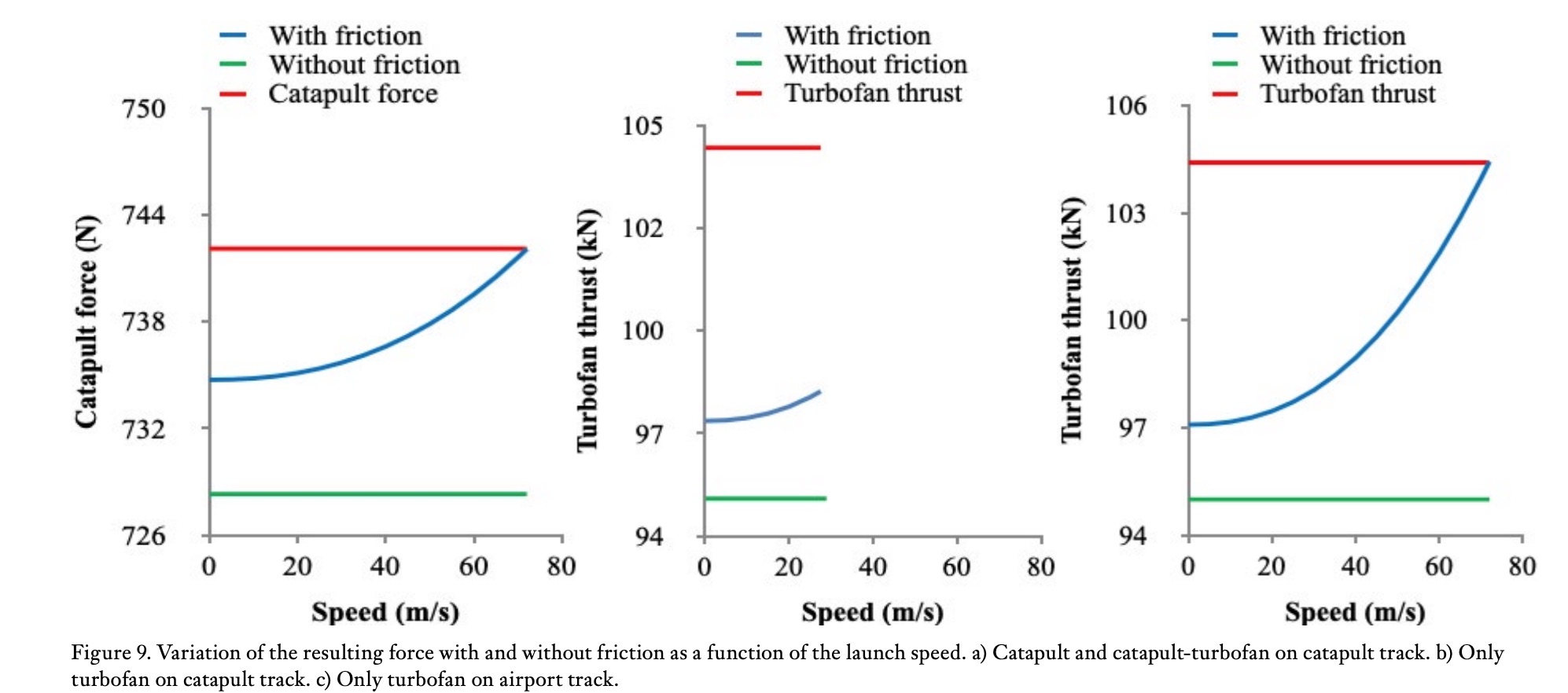 Figure 9a represents the resulting forces required for the FA-18 Hornet launching, considering the action of either the catapult, turbofan or both on the catapult track. Figure 9b considers only turbofan on the catapult track and Figure 9c shows the forces acting on the aircraft in the case of operating just the turbofan on the airport track, as a function of speed in the three cases. In these figures, the cases considering friction and disregarding it are also represented. In Figure 9a there is a slight decrease in the value of the force exerted upwards by the launch bar, resulting in a lower rolling force of 0.3 kN at take off, a negligible value, so the launch Equations for Scenarios (a) and (b) have been considered equal.
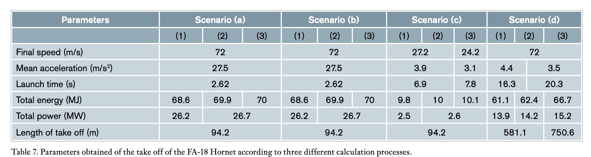
 The results from the take off of the FA-18 Hornet using three different forms of calculus are compared in Table 7: (1) applying the equations of classical physics without friction, (2) considering friction and (3) applying equations (8) and (9) based on the reference (Hernando-Díaz, 2018) for the Scenarios (a), (b), (c) and (d) listed in this same table. The mass of the aircraft and launcher-pistons is considered in Scenario (c) and for Scenario (d) only the mass of the aircraft. Total energy and power include friction. Analysing case (2) with friction, the acceleration achieved and the take off time used by using catapult or catapult-turbofan in Scenarios (a) and (b) was 27.5 m/s² and 2.62 s, while only using the turbofan in Scenarios (c) and (d), the results were 3.9 m/s² (-85.8%) and 6.9-16.3 s (163.3%-522.1%), resulting in an insufficient final speed of 27.2 m/s (-62.2%) for take off in Scenario (c) and an airport take off length of 589.1 m (+525.4%) for Scenario (d). Considering the performance at the rated capacity of the steam catapult and turbofan, a 39739 kg aircraft can be launched at 72 m/s, 68.5% higher mass than the FA-18 Hornet. Obviously, with this capacity, it is also possible to launch heavier aircraft such as the F-35C.
 4. Conclusions
The use of a steam accumulator reduces by 95.6% the thermal power that a steam generator of a nuclear reactor should supply to the catapult at each launch. The operation of all existing elements between the steam generator and accumulator can be continuous, avoiding dangerous thermal stresses and increasing equipment efficiency. It is important to highlight the great capacity for storing thermal energy that the accumulator allows by using saturated water (0.9 kWh/°C*m³ or 260.3 kWh/m³) and supplied in a short time (2.62 s) for each cycle (60 s). The analysis of forces acting during the launch shows that the catapult provides most of the force needed, whereas that provided by turbofans represents a small percentage. Friction forces are small when compared to the force provided by the set of catapult-turbofan system. The steam catapult is presented here as a way to highlight the relevance of steam accumulators in saving energy. In addition, the use of nuclear aircraft carriers greatly favors the use of saturated steam for this application.
5. References
Atalayar. (2021). Available in: https://atalayar.com/ content/estados-unidos-modifica-el-despliegue-del-portaaviones-uss-nimitz-por-las-amenazas-de-ir%C3%A1n. Accessed March 2023.
Biglia A, Comba L, Fabrizio E, Gay P, Aimonino D. (2017). Steam batch thermal processes in unsteady state conditions: Modelling and application to a case study in the food industry. Applied Thermal Engineering. 118: 638-651. https://doi. org/10.1016/j.applthermaleng.2017.03.004.
Elward B. (2010). Nimitz class: aircraft carriers. Osprey publishing Ltd. Available in: www. ospreypublishing.com. Accessed September 2022.
EPA. (1999). Catapult wet accumulator discharges: nature of discharge. Available in: https://www. epa.gov/sites /production/files/201508/documents/2007_07_10_oceans_regulatory_unds_ tdddocuments_appacatapultwe t.pdf. Accessed August 2022.
FA-18 Hornet. (2013). FA-18 Hornet. Available in: http://www.aire.org/hornet/. Accessed December 2022.
F16. (2020). Landing signal officer reference manual (Rev. B). Chapter 10: steam catapults. Available in: http://63.192.133.13/VMF-3121LSO. pdf. Accessed October 2022.
Hernando-Díaz J. (2018). Análisis de la embarcabilidad de aviones de combate terrestres. Tesis Doctoral, UPM Madrid. Available in: http:// oa.upm.es/40985/1/Jose_Luis_Hernando_ Diaz.pdf. Accessed September 2022.
Garstin J. (2016). Hydraulics in flight-deck machinery. Available in: http://citeseerx.ist.psu.edu/ viewdoc/download?doi= 10.1.1.845.194&rep=rep1&type=pdf. Accessed May 2023.
Global security. (2020). Chapter 4: steam-powered catapults. Available in: https://www.globalsecurity.org/military/library/ policy/navy/ nrtc/14310_ch4.pdf. Accessed August 2022.
López JA. (2013). Dinámica longitudinal tracción. Resistencia al avance y diagrama de tracción. Available in: https://docplayer.es/42495424-Dinamica-longitudinal-traccion-resistencia-al-avance-y-diagrama-de-traccion-e-i-i-valladolid-jose-a-lopez-p-1.html. Accessed September 2022.
Muñoz-Navarro MA. (2020). Manual de vuelo. Available in: https://www.manualvuelo.es/1pbav/17ataqu.html+&cd=1&hl =es&ct=clnk&- gl=es. Accessed March 2023.
Naval education and training command. (1974).
Aviation. Boatswain´s mate E1&C. Rate training manual. Available in: https://files.eric.ed.gov/ fulltext/ED109344.pdf. Accessed August 2022.
Navy BMR. (2020). Chapter 5: steam-powered catapults. Available in: http://www.navybmr.com/ study%20material/14310a/ 14310A_ch5.pdf. Accessed August 2022.
Parwate S, Daronde S, Telrandhe S. (2017). Electromagnetic Aircraft Launch System. Vol-3 Issue-2, IJARIIE-ISSN(O)-2395-4396. Available in: http:// ijariie.com/AdminUploadPdf/electromagnetic_aircraft_ launch_systemijariie 4074.pdf. Accessed August 2022.
Quora. (2020). How does a catapult on an aircraft carrier work? Available in: https://www.quora. com/How-does-a-catapult-on-an-aircraft-carrier-work. Accessed August 2022.
SBIR-STTR. (2019). Passive Cooling for Aircraft Carrier Jet Blast Deflectors (JBD). Available in: https://www.sbir.gov/node/1606301. Accessed August 2022.
Spiraxsarco. (2017). Steam accumulators. Available in: http://www.spiraxsarco.com/Resources/ Pages/Steam-Engineering-Tutorials/the-boiler-house/steam-accumulators.aspx. Accessed Jule 2022.
Stevanovic V, Maslovaric B, Prica S. (2012). Dynamics of steam accumulation. Appl Therm Eng, 37: 73–79. https://doi.org/10.1016/j.applthermaleng.2012.01.007.
Stevanovic V, Petrovic MM, Milivojevic S, Maslovaric B. (2015). Prediction and control of steam accumulation. Heat Transfer Eng. 36: 498–510. https://doi.org/10.1080/01457632.2014.935226.
Sun B, Guo J, Lei Y, Yang L, Li Y, Zhang G. (2015). Simulation and verification of a non-equilibrium thermodynamic model for a steam catapult’s steam accumulator. Int J Heat Mass Transf. 85: 88–97. https ://doi.org/10.1016/j.ijhea tmass trans fer.2015.01.120.
Sung W, Hong Y, Wang Y. (2016). Operation Optimization of Steam Accumulators as Thermal Energy Storage and Buffer Units. Energies. Available in: https://www.academia.edu/35033869 / Operation_optimization_of_steam_ accumulators_as. Accessed September 2022.
Swiss Armed Force. (2020). Boeing F/A-18 Hornet. Available in: https://www.vtg.admin.ch/en/ einsatzmittel/luft/fa18-hornet.html. Accessed September 2022.
The Engineering ToolBox1. (2020). Friction and Friction Coefficients. Available in: https://www.engineeringtoolbox.com /friction-coefficients-d_778.html. Accessed August 2022.
The Engineering ToolBox2. (2020). Rolling friction and rolling resistance. Available in: https:// www.engineeringtoolbox.com/ rolling-friction-resistance-d_1303.html. Accessed August 2022.
Wenqiang S, Yuhao H, Yanhui W. (2017). Operation optimization of steam accumulators as thermal energy storage and buffer units. Energies. 10(1) : 1-16. https://doi.org/10.3390/en10010017.
Yang P, Hu X, Liao G. (2017). Dynamic Characteristics of the Steam Accumulator Charging and Discharging. MATEC Web of Conferences 100. Available in: https://www.matec-conferences.org/articles/ matecconf/ abs/2017/14/ matecconfgcmm201703005/ matecconfgcmm201703005 .html. Accessed August 2022.
Zhou Z, Huang J. (2020). An optimization model of parameter matching for aircraft catapult launch. Chinese Journal of Aeronautics. 33: 191-204. https://doi.org/10.1016/j. cja.2019.08.004.