Filler parameters in additive manufacturing
Parámetros de relleno en la fabricación aditiva
Iván Prada Parra, Manuel Domínguez Somonte (1)
Abstract
Additive manufacturing (AM) is the process by which an object is manufactured from a three-dimensional computeraided design model by superimposing layers of material. Although the external appearance is the same, the inside of a part obtained by additive manufacturing can have different structures and infill geometries, due to the fact that this technique allows the inside region of the part obtained to be controlled with great precision. The infill plays a fundamental role in the mechanical properties of the part obtained. In recent years, the relationship between infill and mechanical properties has begun to be investigated and has been reflected in numerous studies. Current 3D printing software allows the selection of different infill patterns and densities, as well as the modification of various parameters, which allow the characteristics of the part to be varied according to its intended use. The purpose of this article is to illustrate the different filler alternatives available, in order to establish some general criteria to help choose the right filler depending on the final use of the part.
Keywords: Additive manufacturing, 3D printing, fused deposition modeling (FDM), infill parameters, infill percentage, infill geometry.
Resumen
La fabricación aditiva (FA) es el proceso mediante el cual se fabrica un objeto a partir de un modelo de diseño asistido tridimensional con la superposición de capas de material. Aunque el aspecto externo sea el mismo, el interior de una pieza obtenida mediante fabricación aditiva puede tener diferentes estructuras y geometrías de relleno, debido a que esta técnica permite controlar con mucha precisión la región interior de la pieza obtenida. El relleno interior desempeña un papel fundamental en las propiedades mecánicas de la pieza obtenida. En los últimos años se ha empezado a investigar la relación entre relleno y propiedades mecánicas, lo que ha quedado reflejado en numerosos estudios. Los programas informáticos actuales de impresión 3D permiten seleccionar diferentes patrones y densidades de relleno, así como modificar diversos parámetros, que permiten variar las características de la pieza según su uso previsto. El objetivo de este artículo es ilustrar las diferentes alternativas de relleno disponibles, con el fin de establecer unos criterios generales que ayuden a elegir adecuadamente el relleno en función del uso final de la pieza.
Palabras clave: Fabricación aditiva, impresión 3D, modelado por deposición fundida, parámetros de relleno, porcentaje de relleno, geometría de relleno.
Recibido/ received: 03/05/2023 Aceptado/ accepted: 20/05/2023
(1) Ingeniería del Diseño. Universidad Nacional de Educación a Distancia (UNED). Juan del Rosal, 12. 28040 Madrid. España.
Corresponding author: Iván Prada. E-mail: iv************@*****il.com
1. Introduction
1.1. Additive manufacturing
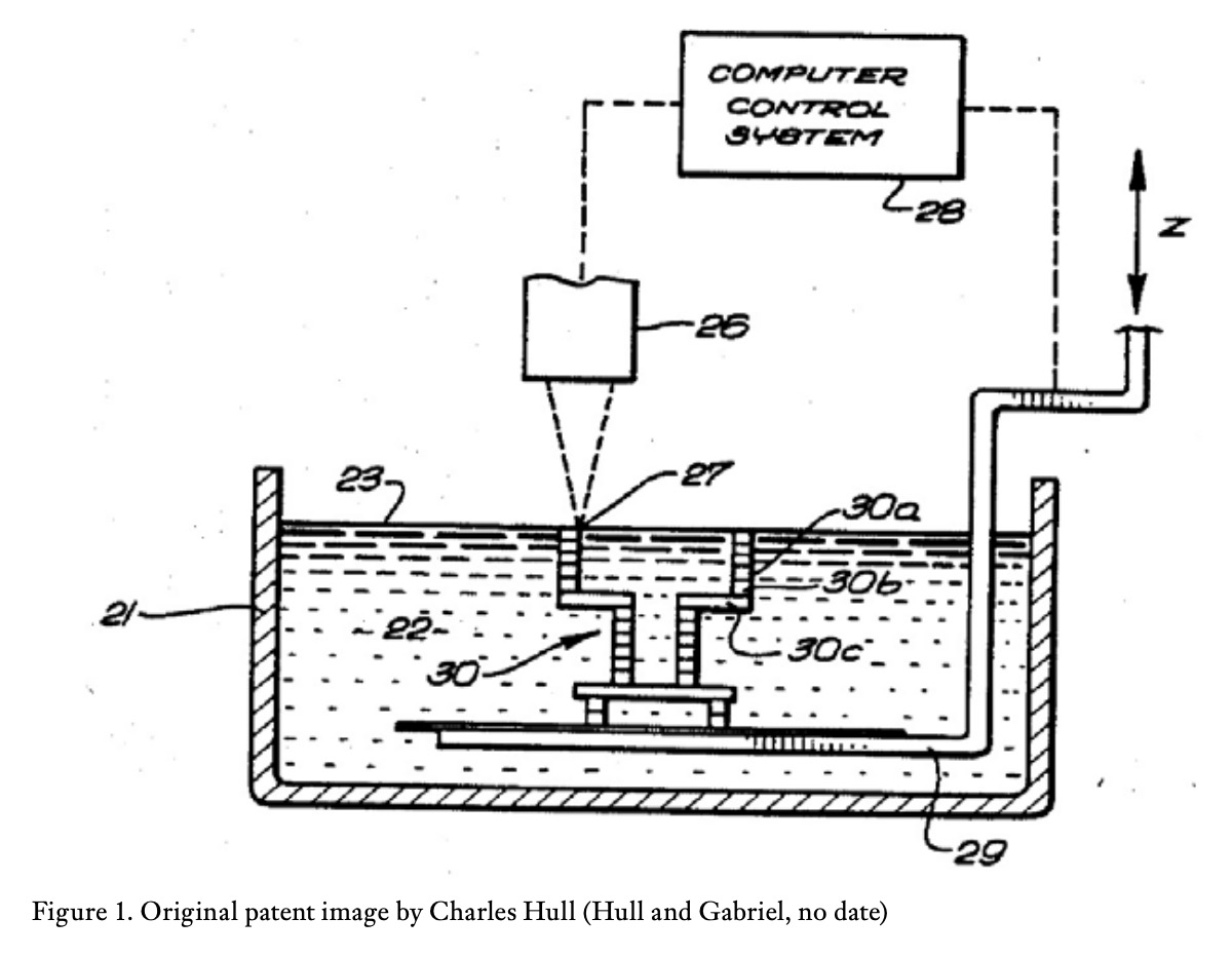
The origin of additive manufacturing dates back to 1976, when Charles Hull invented stereolithography (figure 1), process by which layers of photosensitive resin are solidified by means of a laser (Domínguez et al., 2013). Later, in 1988, the first 3D printing machine was marketed by the company 3D Systems. With this first 3D printer, an ultraviolet laser solidifies a photopolymer in a liquid state, layer by layer, so that threedimensional parts can be built.
This new idea of manufacturing by superposition of layers gave rise to a new stage in the way of approaching the construction of parts, which until then had been based on traditional manufacturing technologies, such as casting, machining or forming.
 Due to the advantages of this new manufacturing concept, such as design flexibility, low waste, the possibility of manufacturing complex geometries, low production cost and speed of construction, various techniques based on manufacturing by superposition of layers have emerged, such as sintering, gluing of paper sheets or plastic extrusion. Each of these technologies has developed and advanced due to the emergence of new materials, process control and increased working speed (Espinosa Escudero, 2013).
Today we can define additive manufacturing as the ”process of creating or fabricating a 3D object directly from a computer-aided design (CAD) model through layer-by-layer manufacturing” (Qamar Tanveer et al., 2022).
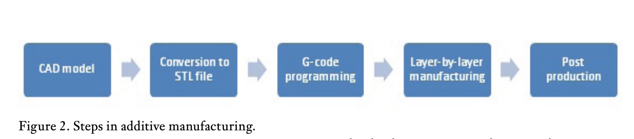 In general terms, the process followed is similar in the different additive manufacturing techniques (figure 2). Firstly, using a 3D computer-aided design program, such as Inventor, Solid Works, Catia, FreeCad or others, a file of the model created is obtained. This file has a specific format depending on the programme used to develop the model.
These files are converted into standard tessellation format (STL format) which contains the geometrical information of the model.
There are several specific programmes that are able to convert the geometry of the STL files into overlay layers, and define how the three-dimensional model is built by adjusting the different parameters according to the additive manufacturing technology used.
These instructions are transmitted to the machine in the form of command lines that refer to the control of the different machine parameters, such as positioning, speeds and temperatures, among others. Nowadays, there has been a tendency to unify the language of communication with the different additive manufacturing machines in the so-called ”G” code, which has become the common language not only in additive manufacturing, but in any other manufacturing equipment operated by numerical control (NC), such as machining machines or laser or water cutting machines (G-code Generator: All You Need to Know | All3DP, no date).
Once the piece is finished, it may or may not be necessary, depending on the technology used, a post-processing process to improve its properties or final appearance.
1.2 Fused deposition modelling
Currently, the most common additive manufacturing technique is called fused deposition modelling (FDM). It is a widespread technique due to its low cost, speed of construction and simplicit.
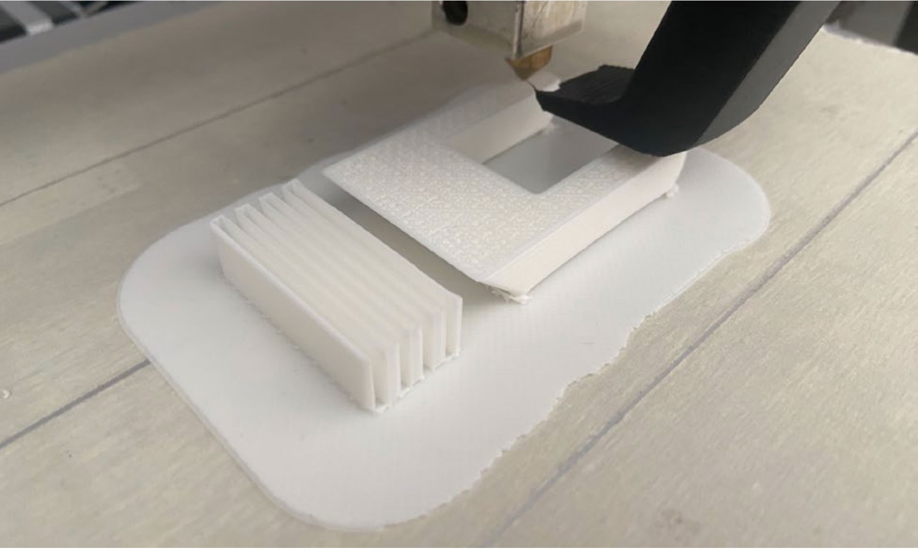
In the FDM process, a thermoplastic material is heated to its semi-molten state and then extruded through a nozzle into a very thin filament, depositing it layer by layer to build the three-dimensional object, following the trajectories defined by a file obtained from the computeraided design program (File:Prusai3- metalframe.jpg – RepRap, no date).
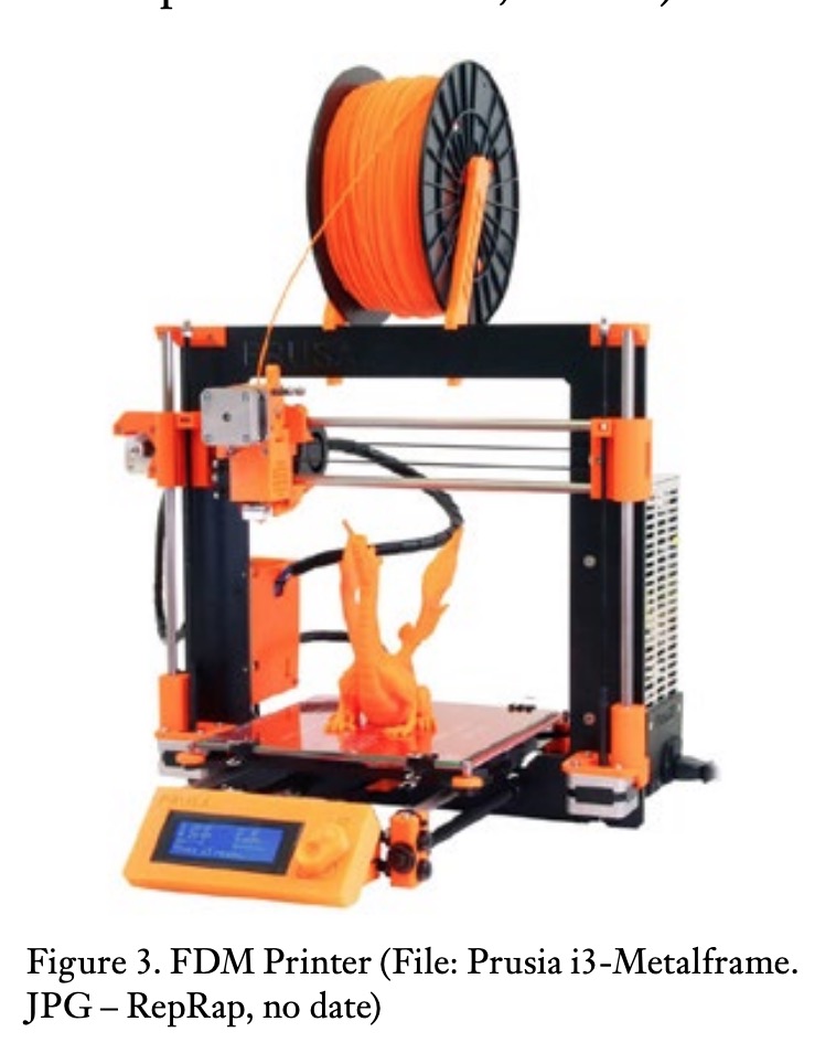 The source material is a continuous wire wound on a bobbin, with a diameter of approximately 1.75 mm, which passes through a feeder that takes it to the extruder nozzle, where it is heated and directed towards a base on which the wires are deposited in a state of semi-melt, which solidifies when it cools on a flat base. The following layer is placed on top of the first, and the two are welded together. The movements of the extruder head and the base are electronically controlled, allowing movements in the three X-Y-Z axes and the three-dimensional construction of the part (figure 3).
This technique was initially used for the rapid production of conceptual or aesthetic prototypes, allowing the designer to have a physical model in a very short time and with a good quality/ price ratio. With the development of new materials and techniques, it is even possible to produce functional or real prototypes, which serve as models for the manufacture of small series of parts. The current trend is towards the manufacture of small series of fully functional parts, using materials with properties appropriate to the final function of the part.
The materials commonly used are thermoplastics such as polylactic acid (PLA) and acrylonitrile butadiene styrene (ABS), as well as eutectic metal alloys (copper, bronze, stainless steel, aluminium, etc.). By using ABS, functional parts can be produced. The use of metal alloy wires requires a postprocessing of sintering and grinding or polishing to achieve the final appearance and properties of the part (Cómo conseguir piezas totalmente metálicas con impresión 3D FDM, no date).
2. Methodology
The methodology used for the development of this article has been based on the search for current and relevant information related to the concepts connected with the filling parameters in additive manufacturing in the field of fused deposition modelling. We have also tried to find information on how these parameters influence the mechanical behaviour of the manufactured part.
Articles related to the topic have been searched in several search engines such as Scopus, the UNED Library, IEEE Xplore or Google Scholar, with the key terms: additive manufacturing, 3D printing, fused deposition modelling (FDM), infill parameters, infill percentage, infill geometry). Finally, after reviewing the articles and information found, a compilation was made of those that seemed most relevant to the proposed topic, in order to proceed to read them and subsequently establish a suitable structure to set out the ideas to be developed in this article.
 2.1 3D Printing process parameters in FDM
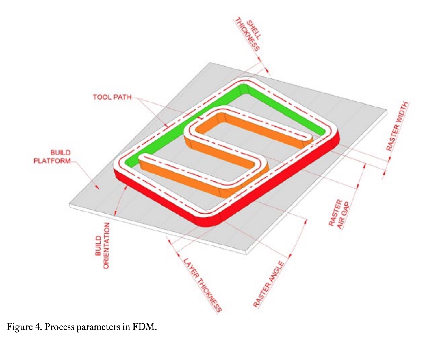
The parameters that define the 3D printing process include layer thickness, extruder and support base temperatures, infill geometry, infill density, weft width, inter-weft gap, weft orientation angle, outer layer thickness, orientation of the part to be built, among others (figure 4) The parameters of the FDM printing process play a fundamental role in the quality and final appearance of the piece obtained, and also in its mechanical properties such as its strength and elasticity (Luis Serrano-Cinchilla, Liliana BustamanteGóez, and Junes Abdul Villarraga-Ossa, 2022). They are also responsible for the anisotropic behaviour of the manufactured part, due to the fact that their composition does not have a homogeneous orientation in all directions (Qamar Tanveer et al., 2022). The mechanical properties of the finished parts are different from those of the source material. (Manuel José Carvajal Loaiza et al., 2020). It is therefore necessary to understand how these different configurations affect additive manufacturing in order to obtain parts that support the loads for which they have been designed.
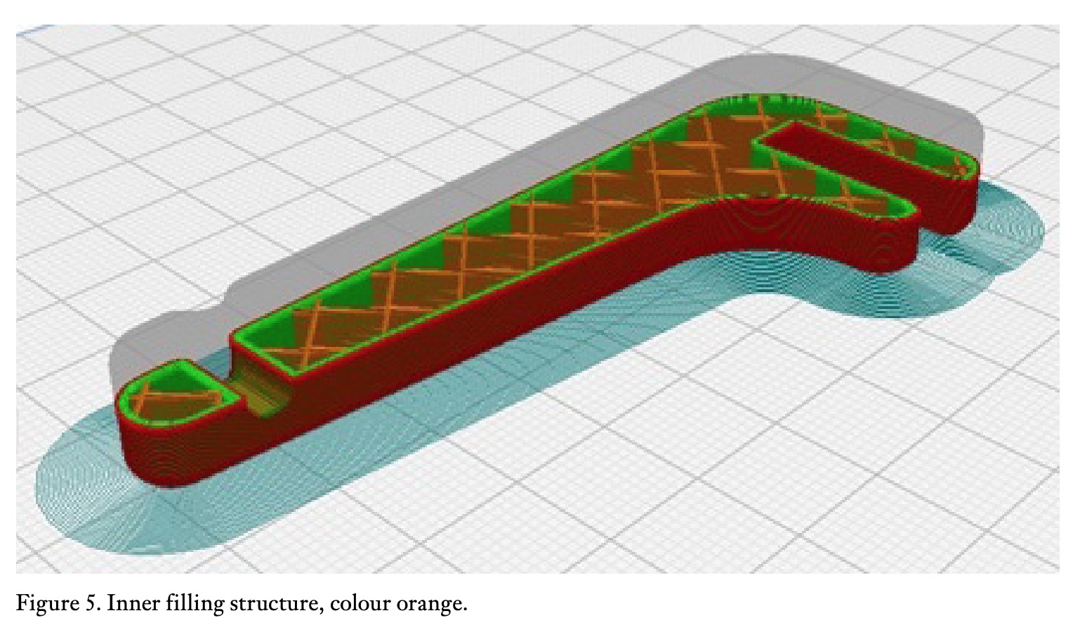 Normally, the parts obtained by this technique are built with an internal structure that is not completely solid, but the interior is formed by a lattice of variable geometry and density, including solid and hollow parts. This is done to save material and printing time, and also because when a part is under load, the stresses are more concentrated on the outer surface than on the inner section of the part (Bergonzi, 2021).
The parameters of the FDM printing process play a fundamental role in the quality and final appearance of the piece obtained, and also in its mechanical properties such as its strength and elasticity (Luis Serrano-Cinchilla, Liliana BustamanteGóez, and Junes Abdul Villarraga-Ossa, 2022). They are also responsible for the anisotropic behaviour of the manufactured part, due to the fact that their composition does not have a homogeneous orientation in all directions (Qamar Tanveer et al., 2022). The mechanical properties of the finished parts are different from those of the source material. (Manuel José Carvajal Loaiza et al., 2020). It is therefore necessary to understand how these different configurations affect additive manufacturing in order to obtain parts that support the loads for which they have been designed.
 Normally, the parts obtained by this technique are built with an internal structure that is not completely solid, but the interior is formed by a lattice of variable geometry and density, including solid and hollow parts. This is done to save material and printing time, and also because when a part is under load, the stresses are more concentrated on the outer surface than on the inner section of the part (Bergonzi, 2021).
2.2 Filler parameters
While conventional manufacturing processes control mainly the outside of the part, additive manufacturing allows for very precise control of both the outer walls and the inner filling of the manufactured object. For example, in conventional plastic injection moulding, we can produce threedimensional parts that are completely solid, or hollow inside, but we cannot produce a mixture of hollow and solid parts mixed together, let alone precisely control the geometry of this structure. However, in additive manufacturing, where the object is built by layering, where the geometry inside the outer shell of the part is built in the same way, layer by layer, it is possible for the inner filling to follow any geometry we want or that the software we are using will allow us to build.
The two fundamental aspects that characterise the filling of an MDF part are:
• The infill geometry
• The infill density
This geometry of the inner filling influences the amount of material to be used and the manufacturing time, and therefore directly affects the cost of the part obtained. But it also directly affects the mechanical properties of the part obtained, an aspect that is essential to control when it is going to be used in real applications, where the part will be subjected to stresses during its use.
 The correct selection of the configuration of the internal filling is what makes it possible to replace conventional parts with parts obtained by additive manufacturing with equivalent properties.
2.3 The infill geometry
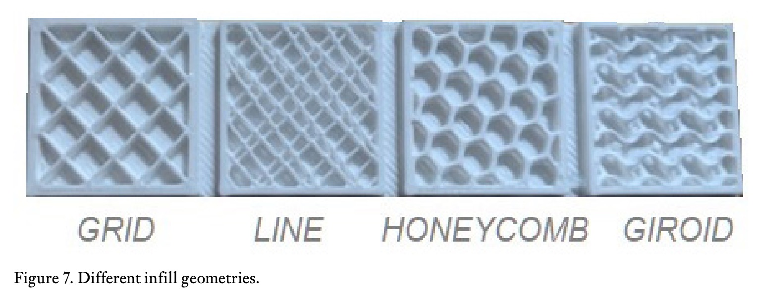
The infill geometry is the shape of the inner material structure of the part (figure 7). It can be a very simple or more complex structure, and affects the strength of the part, its weight, printing time and also its flexibility.
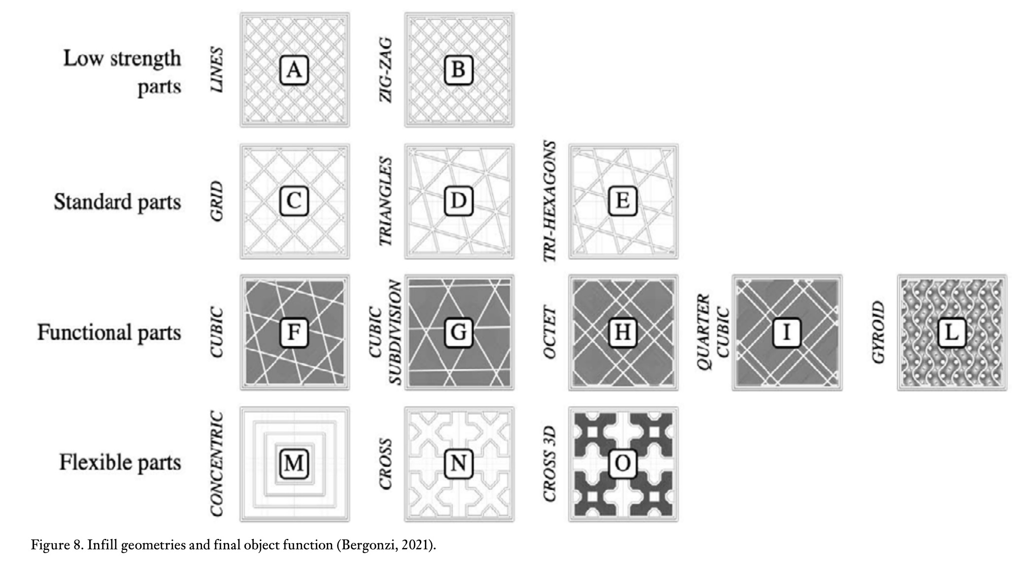
Some geometries provide better properties than others for specific part functions. By connecting to each other, and in turn connecting and joining the outer casing of the part, the different geometries provide different characteristics, such as lightness, greater resistance to certain loads, greater or lesser elasticity, among others (figure 8). In general terms, the following characteristics can be established for the different types of geometry:
• Lines: line-shaped geometries contain lines printed in one direction along the X or Y axis every other layer. It provides strength only in two dimensions and is suitable for fast printing. It uses little material so the parts obtained are lightweight. Figure 7. Different infill geometries.
• Honeycomb (or hexagons): produces a hexagon structure that looks like the cells of a honeycomb. Fast to medium print times and moderate resistance are achieved.
• Grid: similar to the line pattern, but contains lines in two directions in each layer, so the connections are larger, even though they are strong only in the X and Y directions. Fabrication time and material consumption are average.
• Triangles: composed of triangular lines superposed in the X-Y plane. Only provides strength in two directions, but is acceptable when increasing the junction points between the inner geometry and the outer walls of the part.
• Tri-hexagons: consists of triangular lines in the X-Y plane, creating hexagonal patterns with triangles in the middle of the hexagons. It provides acceptable two-dimensional strength by increasing the attachment points between the structure itself and with the outer walls of the part.
• Cubic: this geometry consists of stacked cubes, which are placed at an angle of 45° to the horizontal plane (X-Y plane). It provides excellent strength in all three dimensions, but requires more material and printing time.
• Octet: similar to the cubic pattern, but materialises in the form of stacked square pyramids. It has strength in all three dimensions and is suitable for parts requiring strength.
• Giroid: includes irregular concave curvatures that intersect each other. It strikes a balance between strength, material quantity and printing time.
• Concentric: a 2D pattern that generates lines parallel to the outer walls of the part. It allows parts to be made with some flexibility. It is a pattern that is quick to print and requires less material than most patterns.
• Cross: is another 2D pattern that generates grids from crosses. The hollow spaces between the grids and the crosses give the part flexibility.
In general terms, the recommendations set out in the table 1 for the selection of the infill geometry.
 2.4 Infill density
The infill density refers to the solid part of the inner structure of the part, and is expressed as a percentage between 0%, i.e. all hollow interior, and 100% indicating that the interior is completely solid (figure 9).
The percentage of filler directly influences the amount of material used in its manufacture: the higher the percentage of filler, the lower the percentage of voids and therefore the heavier the finished piece.
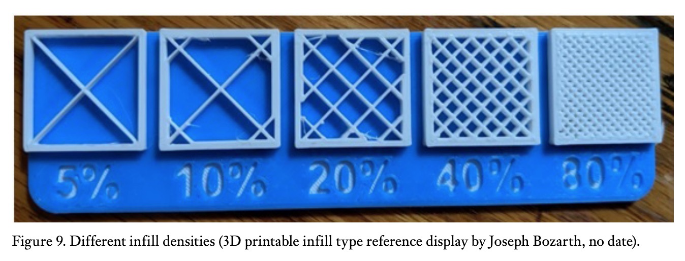 The fill density also influences the printing time as well as the mechanical properties of the finished part. When selecting the percentage of filler, it is important to know the use of the part and the properties it requires (table 2).
For visual or aesthetic parts that have no mechanical requirements other than the external appearance, a filler percentage between 0% and 15% can be considered. This allows for material savings and fast printing, and will result in very light parts with low mechanical strength.
For most conventional parts, where high mechanical strength is not required, percentages between 15% and 50% would be most suitable. This leads to average printing times and material consumption. For functional parts requiring mechanical strength, it is necessary to increase the solid parts of the part and decrease the voids. Suitable percentages are between 50% and 100%. The printing time, material consumption and weight of the part will be high.
For printing parts where flexibility is desired, the higher the percentage of filler, the lower the flexibility for a given filler pattern. Flexible printing materials such as thermoplastic polyurethane (TPU), thermoplastic elastomers (TPE), thermoplastic copolyester (TPC), thermoplastic polyamide (TPA) or soft PLA make it possible to print flexible parts with good mechanical strength.
 3. Infill parameters with Cura
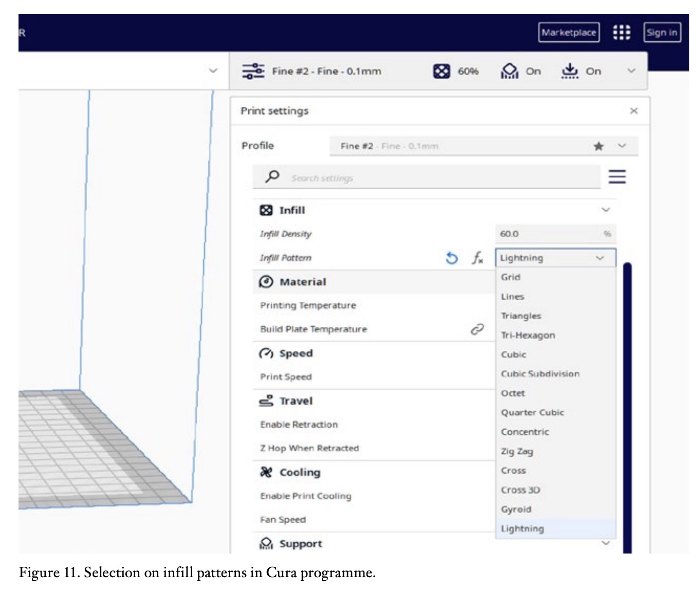
Current 3D printing programs have initial fill settings that work well for most parts, but allow you to adjust different parameters when you need to obtain different properties, either in the sense of saving time and material increase the strength of the part or provide a special quality such as flexibility.
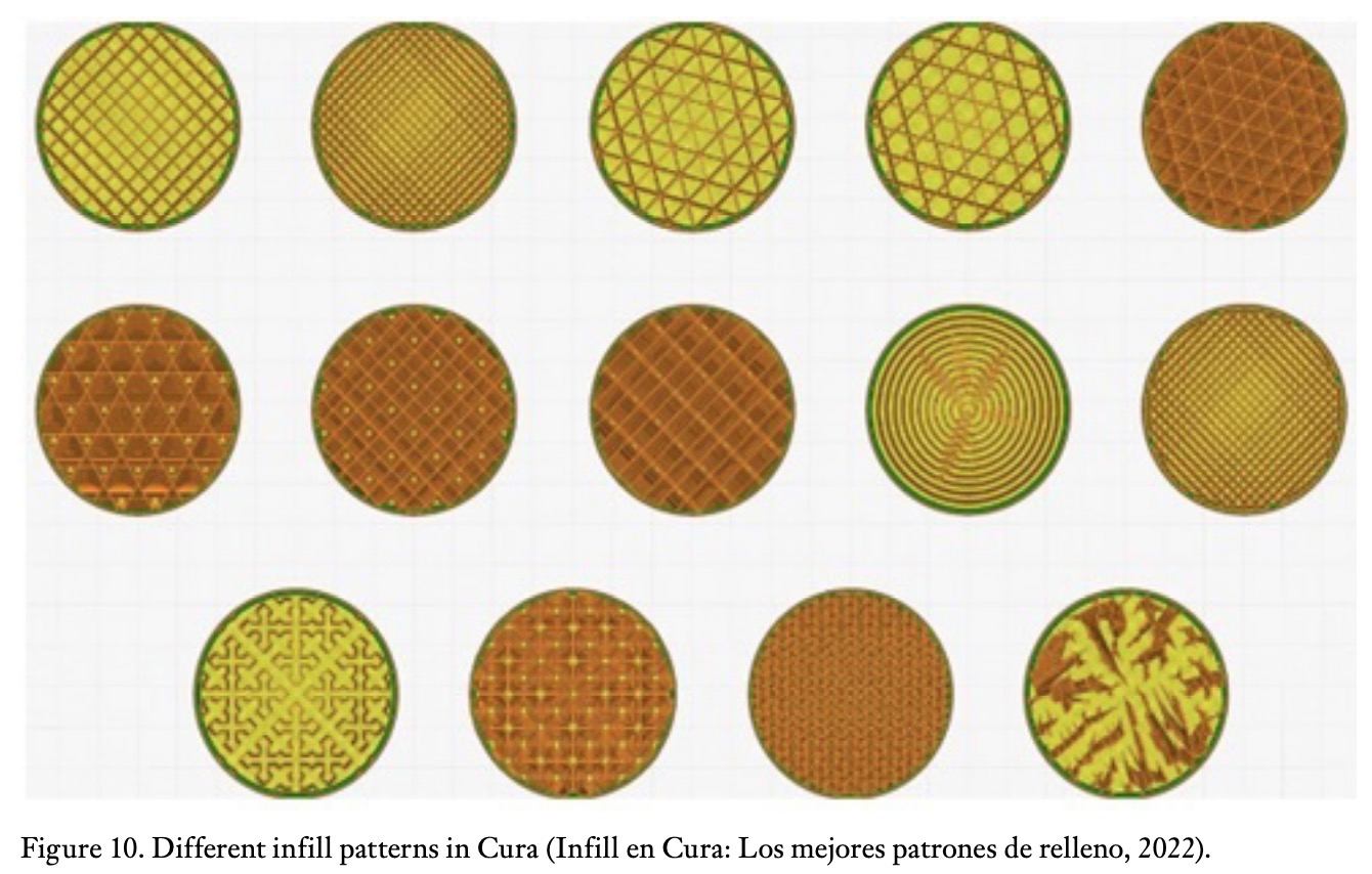
One of the most widespread programmes in the fused deposition modelling technique is Cura, which in its latest version 5.3 offers 14 possible infill geometries, shown in the figure 10.
Cura recommends selecting the filler configurations listed in the table 3 (Infill en Cura: los mejores patrones de relleno, 2022).
4. Gradual infill in Z-axis
Although it may be thought that the infill inside the part should be uniform, this does not necessarily have to be the case. In order to optimise the use of the filling material in the workpieces, several techniques have been established.
One of them is the so-called gradual filling, which is offered by the Cura programme. This is a variable infill in the Z-axis (vertical printing axis, i.e. axis perpendicular to the substrate where the part is printed). The density of the infill increases in the upper part of the print with respect to the lower part, and the printing time is reduced.
5. Different densities and types of infill in one piece
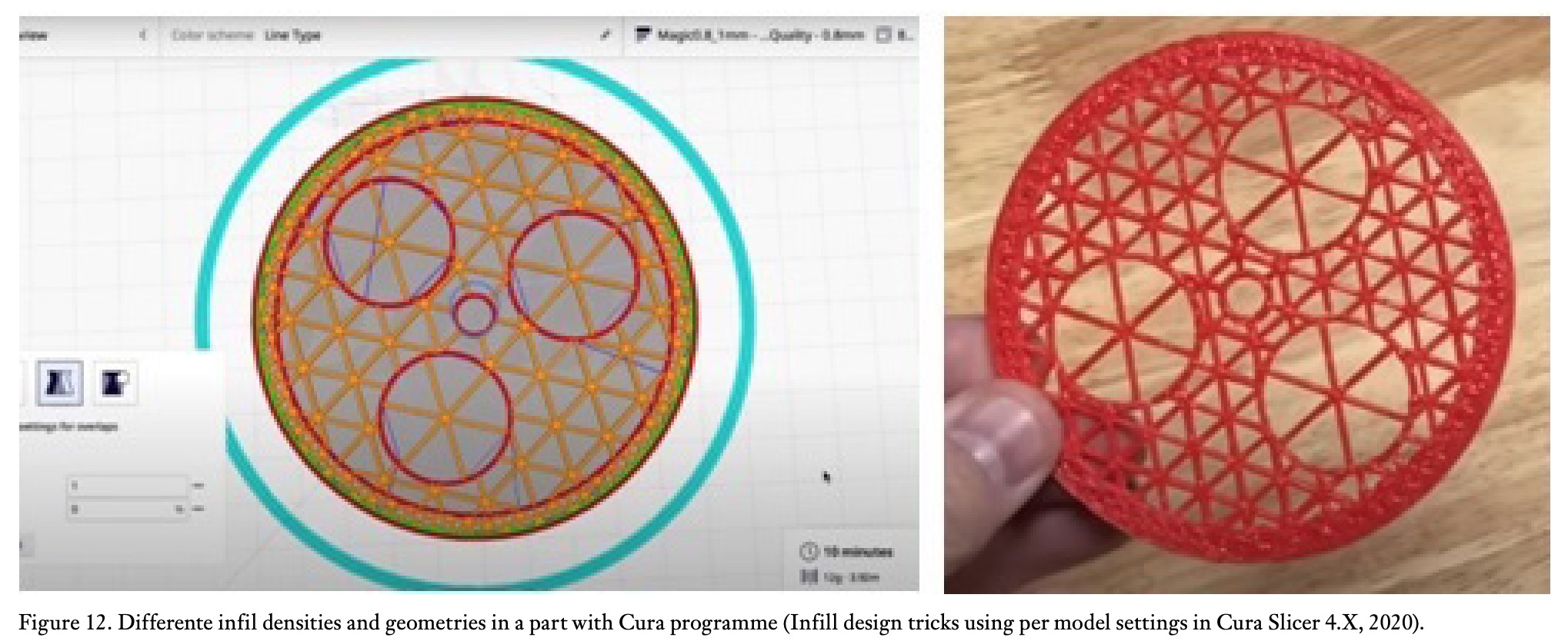
The Cura programme also allows different fill densities and geometries to be included in the same part, allowing for a customised internal structure (figure 12). This requires prior work in the programme to establish the desired configuration.
 6. Gradient infill and variable infill as a function of local stresses
With the so-called gradient filling, the density of the filling can be set so that it is higher towards the perimeter, where the stresses are concentrated, and lower as you get closer to the inside of the part (figure 13). This is intended to improve mechanical strength properties while using less material and taking less time to manufacture.
This technique is useful for incorporating filler material in those areas where it is really needed. By using computer-aided design software, it is possible to establish a study of the stresses in a loaded part (figure 14). The results will tell the designer in which areas more material is needed, because there are higher local stresses, and in which areas it is not necessary.
Once the different configurations of the densities of the internal filling, due to these local stresses, are known, using the gradient filling technique it is possible to manufacture a part with a completely optimised internal distribution of the material so that it can support the loads to which it is subjected by placing the material where it is needed.
This variable distribution of filler densities and geometries is something that can be done with additive manufacturing, due to its very nature, but it cannot be done with conventional manufacturing methods. This is a huge advantage of additive manufacturing over conventional manufacturing.
 7. Conclusions
Additive manufacturing, which in its early days was mainly intended for the rapid manufacture of prototypes or visual or aesthetic parts, is increasingly being used to manufacture functional parts or even small series. The simplicity of the process, the ease of customisation of designs, the speed and low cost are making it possible to replace parts obtained by conventional methods with parts obtained by 3D printing.
For this, it is essential to know how the parameters of the printing process affect the physical behaviour of the printed part. 3D printed parts have an anisotropic behaviour, due to the manufacturing process itself layer by layer and the different orientations and densities of its internal structure. This behaviour can limit the applicability of additive manufacturing techniques compared to conventional manufacturing, where the behaviour is generally isotropic and more predictable.
The stresses in a loaded part flow mainly through the outer surface, but it must also be verified how these stresses flow along its internal structure. On the other hand, the data supplied by the manufacturers of the base materials, such as PLA, are insufficient to predict the behaviour of the manufactured part, since the additive manufacturing process involves a multitude of variables that affect the mechanical properties of the finished part. Several studies and practical tests have shown the fundamental role that filler geometry and filler density play in the physical behaviour of the part, and some general criteria can be established for the selection of these filler parameters when manufacturing the 3D printed part, which have been presented in this article.
On the other hand, by applying advanced design techniques such as finite element stress analysis, it is possible to determine the internal stresses of a loaded part. Combining this analysis with the possibility offered by the latest additive manufacturing techniques in terms of the variable configuration of the internal filling, it is possible to optimise the material used and place it where it is really needed, with the consequent savings in materials and manufacturing time, as well as improvements in the reliability and safety of use of real parts.
This feature is an undisputed advantage over conventional manufacturing.
However, given that these techniques are currently in the process of maturing, in addition to carrying out theoretical studies, it is advisable to carry out real load tests on parts obtained by additive manufacturing in order to check their real behaviour.
References
3D Printable Infill Type Reference Display by Joseph Bozarth (no date). Available at: https://www.myminifactory.com/ object/3d-print-infill-type-reference-display-94778, https://www.myminifactory. com/object/3d-print-infill-type-reference-display-94778 (Accessed: 3 April 2023).
Bergonzi, L. (2021) ‘Different infill geometry influence on mechanical properties of FDM produced PLA’, IOP conference series. Materials Science and Engineering, 1038(1), pp. 12071-.
Cómo conseguir piezas totalmente metálicas con impresión 3D FDM (no date). Available at: https://filament2print. com/es/blog/70_sinterizado-piezas-metalicas-impresion-3d-fdm.html (Accessed: 2 April 2023).
Domínguez, I.A. et al. (2013) ‘Impresión 3D de maquetas y prototipos en arquitectura y construcción’, Revista de la construcción, 12(2), pp. 39–53. Available at: https://doi.org/10.4067/S0718- 915X2013000200004.
Espinosa Escudero, M. del M. (2013) Ingeniería concurrente. 2a ed. Madrid: Asociación de Ingeniería y Diseño Asistido (AIDA – Instituto de Ingeniería e Innovación Industrial).
File:Prusai3-metalframe.jpg – RepRap (no date). Available at: https://reprap.org/ wiki/File:Prusai3-metalframe.jpg (Accessed: 2 April 2023).
G-code Generator: All You Need to Know | All3DP (no date). Available at: https:// all3dp.com/2/g-code-generator-allyou-need-to-know/ (Accessed: 2 April 2023).
Gradient Infill for 3D Prints (2020) CNC Kitchen. Available at: https://www. cnckitchen.com/blog/gradient-infill-for-3d-prints (Accessed: 25 March 2023).
Hull, C.W. and Gabriel, S. (no date) ‘(54) APPARATUS FOR PRODUCTION OF THREE-DMENSONAL OBJECTS BY STEREO THOGRAPHY’.
Infill Design Tricks using Per Model Settings in Cura Slicer 4.x (2020). Available at: https:// www.youtube.com/watch?v=xc-6xVB9H4I (Accessed: 25 March 2023).
Infill en Cura: los mejores patrones de relleno (2022) All3DP. Available at: https://all3dp.com/es/2/infill-cura-relleno-impresion-3d/ (Accessed: 25 March 2023).
Infill settings (no date). Available at: https://support.makerbot.com/s/article/1667411002588 (Accessed: 5 April 2023).
Luis Serrano-Cinchilla, Liliana Bustamante-Góez, and Junes Abdul Villarraga-Ossa (2022) ‘Influencia de la densidad y de los parámetros de relleno en las propiedades mecánicas compresivas de probetas fabricadas en manufactura aditiva de PLA’, Revista UIS Ingenierías, 21(2). Available at: https://doi.org/10.18273/revuin. v21n2-2022009.
Manuel José Carvajal Loaiza et al. (2020) ‘Influencia de la posición de impresión y la densidad de relleno en las propiedades mecánicas de probetas fabricadas en ABS’, Revista ingenierías (Medellín, Colombia), 19(37), pp. 179–193. Available at: https://doi.org/10.22395/rium. v19n37a9.
Qamar Tanveer, M. et al. (2022) ‘Effect of infill pattern and infill density on mechanical behaviour of FDM 3D printed Parts- a current review’, Materials today : proceedings, 62, pp. 100–108. Available at: https://doi.org/10.1016/j. matpr.2022.02.310.