Damages that can occur in a structure due to an inappropriate design
Daños que pueden producirse en una estructura por un diseño inadecuado
Abstract
Currently, the power of structural calculation offered by com-mercial programs for finite element structural calculation and matrix calculation of bar structures make it possible to mo-del and analyze complex structural forms, both linearly and non-linearly, solving the problem of obtaining the loads exer-ted and displacements experienced with very high accuracy. Nevertheless, the misuse that is made nowadays of the cal-culation programs mentioned above is frequent, the simplest fundamentals of structural mechanics being ignored, in what is beginning to be called “The Computer Pathology in the De-sign and Analysis of Structures”. This power of structural calculation has resulted in the design of more slender and lightweight structures, but new problems are derived from this, both present and future, which can be classified into two groups: On the one hand, all those problems emanating from dynamic processes (earthquakes, wind, etc.) and even associated with fatigue (machinery, elevators, etc.), and on the other hand, those related with non-optimal design, motivated by some structural computer pathology. These de-sign defects can accentuate the negative behaviour of struc-tures subjected to dynamic loads of seismic type. In this paper, some frequent cases are mentioned which are illustrated by photographs, comments and related recom-mendations.
Keywords
Pathology of structures; seismic design recommendations
Resumen
En la actualidad, la potencia de cálculo estructural que ofrecen los programas comerciales de cálculo de estructuras por elementos finitos y cálculo matricial de estructuras de barras hace posible modelizar y analizar, tanto de forma lineal como no lineal, formas estructurales complejas, resolviendo el problema de obtener los esfuerzos que soportan y los desplazamientos que experimentan, con una exactitud muy alta. A pesar de todo, es frecuente comprobar el mal uso que se hace hoy en día de los programas de cálculo citados, de espaldas a los fundamentos más simples de la mecánica estructural, en lo que se está comenzando a llamar como “la patología del ordenador en el diseño y análisis de estructuras”. Esta potencia de cálculo estructural, ha dado lugar a la concepción de estructuras más esbeltas y ligeras. Sin embargo, de las mismas se derivan nuevos problemas, presentes y futuros, los cuales se pueden clasificar en dos grandes grupos. Por una parte, estarían todos los que emanan de procesos dinámicos (terremotos, viento, etc.) e incluso asociados a fatiga (maquinaria, ascensores, etc.), y por otra, los relacionados con un diseño no óptimo, motivados por una cierta patología informática estructural. Estos defectos de diseño pueden acentuar el comportamiento negativo de estructuras sometidas a acciones dinámicas de tipo sísmico. En el presente trabajo, se mencionan algunos casos frecuentes, los cuales se ilustran mediante fotografías, comentarios y algunas recomendaciones.
Palabras clave
Patología de estructuras, recomendaciones de diseño sismorresistente
Recibido / received: 07.05.2018. Aceptado / accepted: 29.10.2018.
Introduction
“Plan first; then build”. Even though it may seem logical, this approach in the completion of the execution of all types of buildings and civil works is entirely false, being that, even for the most common buildings, form plotting requires prior knowledge of the means of execution.
The completed work must verify certain structural criteria:
• Stability.
• Resistance.
• Deformation.
Habitability can also be included, and the entire set of facilities that are part of the building. The structural designer conceives these criteria based on two fundamental factors: shape and materials; if it is not possible to conceive an optimal design, then it is necessary to use the material strength to achieve balance and harmony in the stability of the structure against the external actions that act upon it (Regalado, 1998).
Currently, the second option has become overused, resulting in designs –not only construction designs, but mainly structural– conceived with a lack of technical common sense.
On the other hand, and on the subject of pathology of structures in general, it seems to be confirmed that project errors are the main reason for this damage and, out of these, calculation errors are not the most significant ones, but instead, as it has been mentioned, the most influential errors come from wrong design and construction concepts and the lack of definition of the work to be done with sufficient detail.
The introduction into the lexicon of the term constructive pathology is very recent, originating in the mid90s. Unfortunately though, it is sometimes used incorrectly. It is a source of surprise and confusion to see some professionals refer to the faults or failures in structure in the following way: “pathologies present in the structure …” or when speaking of a building: “the pathologies observed in the building … “, forgetting that pathology is a part of science that deals with the study of diseases, and not the diseases themselves. Prof. Lozano Martínez-Luengas (Martínez, 1999), with respect to the methodology of the previous diagnosis of the pathology of structures and construction, indicates that:
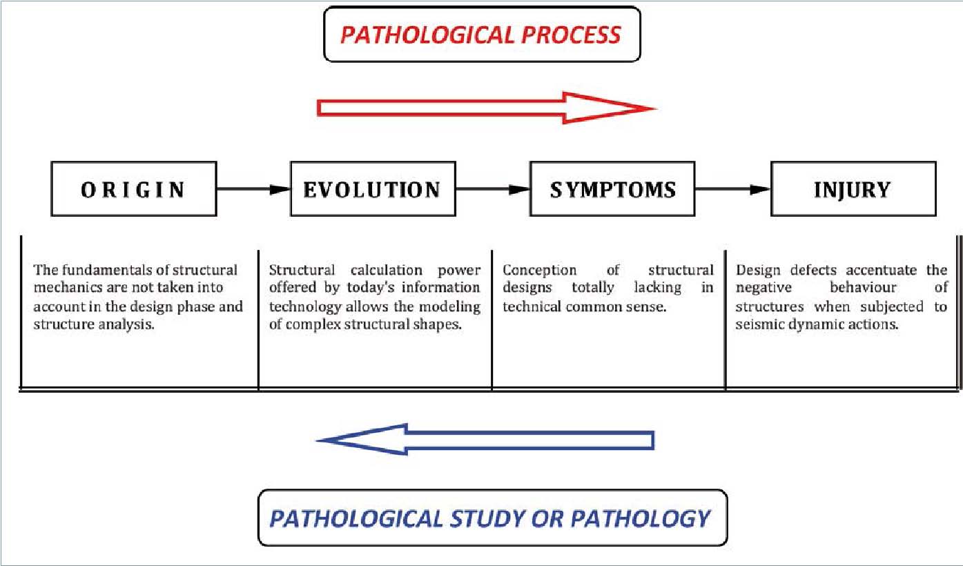
The disease of a living being or a construction is a pathological process that begins with a sickness, which later evolves and manifests itself through a series of symptoms and that, if it is not tackled promptly, ends in injury. This process has been synthesized in Figure 1.
Once the injuries appear, but preferably once the symptoms are detected, the pathologist works in the pathology or pathological study. Following a reverse process to the one described, he studies the nature of the disease: that is to derive the origin of the evil from the injuries and symptoms detected (Fig. 1).
This analysis, called pathological study or pathology, acquires a significant importance when it comes to ruling on the design of a structure (Villa, 2013) located in an area with a certain seismic risk, through a first visual inspection of its structural skeleton.
To illustrate this work, we have chosen an expert opinion regarding a building with a rather particular skeleton design. A summary of a biased extract of this expert opinion related to the topic at hand is presented here. Obviously, names of people and places have been omitted and/or altered. Likewise, the checks described in the annexes are not shown here.
It is a building erected in 2012 that mainly consists of beach-front luxury homes. It has 9 floors above ground level and 2 underground floors reserved for parking space. There are shops in the ground and first floors, offices also in the first floor, and there are homes in the rest of the building.
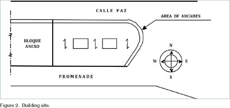
The floor plan of the block is substantially trapezoidal (Fig. 2), with its height matching one of the sides, corresponding to a partition wall perpendicular to both bases. The opposite corner at its longest base has a certain radius of curvature. Therefore, it possesses no floor plan axis of symmetry.
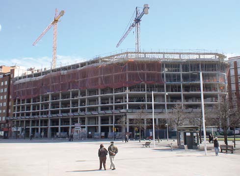
The main facade (facing south) overlooks the promenade (Fig. 3) and the back facade (facing north) overlooks calle Paz. In the latter, the building joins with an area of arcades for pedestrians (about 5.5 m wide), which extends along its entire length, all around the building to the promenade (Fig. 2).
The supporting structure, which is highly partitioned, as corresponds to a housing building, is made up of reinforced concrete frames. The slabs are one-way, made from ceramic reinforced in the perpendicular direction to the main facades. The foundations of the infrastructure are semi-deep, made from reinforced concrete; their perimeter is determined by basement walls and strip footing, while inside this perimeter, pillars rest on isolated footings. The bracing of all the footing is entrusted to the tie beams that follow two orthogonal directions to the floor plan.
Depending on the location of the construction, a basic seismic acceleration ab/g = 0.17 will correspond to it in the seismic hazard map (NCSE-02, 2002); being g the gravity acceleration.
Items affected by the vertical component of the seismic action
Since the direction of occurrence of an earthquake can be completely arbitrary with respect to the structure, in order to study its effects normally the ground acceleration is decomposed into three components: two horizontal directions orthogonal to each other (horizontal longitudinal and horizontal transverse to the floor of the building) and a third vertical direction, perpendicular to both of the above (Villa, 2004a; Ramírez, 2002). Peak vertical accelerations are often between 1/3 and 2/3 of the value of peak horizontal acceleration. In turn, typical accelerations may exceed gravity. To date, stresses caused by the vertical seismic forces have generally been ignored, with the exception of beams of large spans and cantilever beams -their own periods of vertical oscillation are close to those of quakes- (EAE, 2011; NCSP-07, 2007; UNE-EN 1998-2: 2012); undoubtedly because of being unknown, because if the magnitude of the vertical component of the earthquake has an appreciable value, it can generate significant vertical forces (Villa, 2002).
Both the Spanish seismic regulations NCSE-02, and the document that will replace the Eurocode 8, represent the vertical component of the seismic action with the response spectrum, as defined for the horizontal seismic action, but with the ordinates reduced (Villa, 2006):
• Eurocode 8: spectral ordinates are reduced between 30% and 50%, depending on the period of vibration
(Villa, 2004b).
• NCSE-02: prescribes the reduction of spectral ordinates down to 70% regardless of the period (Villa, 2004c). Figure 4 shows how the entry to the parking space in the lower floors is resolved. By cutting two rows of pillars, the vertical forces accumulated in them in the top 8 floors are transmitted to a large edge beam, which supports large concentrations of stress according to its main axis of inertia, and which has greater flexural stiffness.
This situation is worsened by the horizontal thrust that the slab can exert on the head of the large edge beam.
For the calculation of deep beams (or wall beams) formulas used in ordinary beams are not valid, as the assumptions that were used for their deduction (Bernoulli’s plane strain, Saint-Venant’s Principle) are not applicable to the deep beams, as their resistance mechanism is totally different. The flexural strength of these is usually much larger than necessary, while their resistance to shear or the possibility of transverse buckling of the compressed head may impose limitations on their width (UNE-EN 1998-1:2011/A1:2013).
In turn, the pillars in V (Fig. 4) transmit a huge horizontal component to the bottom of the large edge beam, conditioned by the 8 floors they are supporting above them.
In Figure 5, you can see the lack of continuity of a pillar on the ground floor, which supports the loads transmitted by another, 8 floors above it, with a certain eccentricity, and working as a cantilever.
The most significant negative consequences of this design, focusing on seismic resistance, are:
• The deep beams and cantilevered pillars create a discontinuity in the vertical stiffness of the resistant framework (Villa, 2004a).
• Both solutions -as well as the pillars supported by beams- induce vertical loads on these elements, regardless of whether the earthquake has a vertical component, but being substantially more significant in the case that it does (Villa, 2009).
In Figure 6, an alignment of pillars on the facade is interrupted in the first floor by a large edge beam, supported in turn by pillars on the ground floor, which do not match those from the upper floors, is shown.
The stiffness present in these designs against fragile fatigue means that they should be totally banned in seismic zones.
Vertical layout
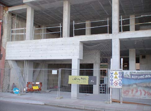
The beginning of the line of arcades which provide cover for pedestrian traffic in the side wall is shown in Figure 7. One aspect of particular importance in order to avoid stress concentrations is to avoid sudden changes in elevation stiffness (NCSE-02, 2002); i.e. the geometric arrangement at great heights should be as regular as possible, carrying out gradually the transitions of shape and/or stiffness, where appropriate, between one floor and the next. Thus, the emergence of local damages from the quake which are motivated by these stress concentrations (UNE-EN 1998-3:2012/AC:2014) is avoided. In this regard, designs with intermediate ground floors where pillars of different lengths would be present (UNE-EN 1998-5:2011) should be avoided.
If the horizontal direction of oscillation of the earthquake coincides with the alignment of the pillars of the arcades, greater displacements should be expected along this direction as a result of a greater flexibility (Bozzo y Barbat, 1995). A solution of this kind may require a ductility of the columns so high that it could even exceed their capacity. In earthquake engineering, this case is known as weak floor (Villa, 2004a).
Vertical expansion joints
In Figure 8, pillars which do not coincide vertically with the deep beam, nor with the vertical expansion joint, can be seen. This last element has an eccentricity of around 1 m, separated in two different planes.
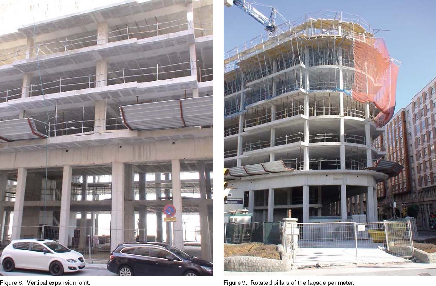
In order to avoid stress concentrations and local damage from the earthquake, geometric arrangements at great heights should be as regular as possible; in this regard, the expansion joints must be contained in a single vertical plane (Fig. 8) (EAE, 2011; UNE-EN 1998-1:2011/A1:2013; UNE-EN 1998-3:2012/AC:2014).
Supports rotated with respect to the main directions of the slabs
As it has been mentioned, the floor plan of the building studied presents, along part of its perimeter, a segment with a certain radius of curvature (Fig. 9). On that circular segment, the rotated placement of the columns with respect to the main directions of the slabs on the path in which the main horizontal displacement is presumed to appear in case of an earthquake, increases the seismic vulnerability the building (Villa, 2004a; Villa, 2009; UNE-EN 1998-3:2012/AC:2014).
Conclusions
Specialists in design agree unanimously in that, in the design of earthquake-resistant buildings, typologies applied should have the highest possible ductility; i.e. they should deform easily, without suffering a significant decrease in resistance. The solutions analyzed generate a serious intrinsic predisposition to suffer damage upon the occurrence of an earthquake of a certain severity, i.e., they constitute a structural vulnerability and should not be allowed in seismic areas.
References
Bozzo, L. M., Barbat, A. H. Diseño Sísmico de Edificios de Hormigón Armado. Monografía CIMNE IS-15, 1995.
EAE Instrucción de acero estructural, Ministerio de Fomento, España, 2011.
Martínez Luengas, L. Síndrome del Edificio Húmedo, Procesos Patológicos, Patología y Terapéutica de Intervención, Tesis Doctoral, Universidad de Oviedo, 1999.
Norma de Construcción Sismorresistente NCSE
02. Parte General y Edificación. Ministerio de Fomento, España, 2002. Norma de Construcción Sismorresistente: Puentes NCSP-07. Ministerio de Fomento, España, 2007.
Ramírez Masferrer, J. A. Efectos de los terremotos sobre las estructuras. Estructuras sismorresistentes. Ed. Fundación Gómez-Pardo, 2002.
Regalado Tesoro, F. Breve Introducción a las Estructuras y sus Mecanismos Resistentes. Ed. CYPE Ingenieros, 1998.
UNE-EN 1998-1:2011/A1:2013 Eurocódigo 8: Proyecto de estructuras sismorresistentes. Parte 1: Reglas generales, acciones sísmicas y reglas para edificación, 2013.
UNE-EN 1998-2: 2012 Eurocódigo 8: Proyecto de estructuras sismorresistentes. Parte 2: Puentes, 2012.
UNE-EN 1998-3:2012/AC:2014 Eurocódigo 8: Proyecto de estructuras sismorresistentes. Parte
3: Evaluación y adecuación sísmica de edificios, 2014.
UNE-EN 1998-5:2011 Eurocódigo 8: Proyecto de estructuras sismorresistentes. Parte 5: Cimentaciones, estructuras de contención y aspectos geotécnicos, 2011.
Villa García, L. M. Algunas consideraciones sobre la futura instrucción de acero estructural EAE en lo referente al proyecto de estructuras sismorresistentes. DYNA Ingeniería e Industria, volumen 84-5 (jun. 2009) 393-402.
Villa García, L. M. Analogía de las normativas sismorresistentes española y europea. Técnica Industrial, no 261 (2006) 27-32.
Villa García, L. M. Aplicación de la Futura Normativa de Construcción Sismorresistente Europea. DYNA Ingeniería e Industria, volumen LXXIX, nº 8 (Nov. 2004) 35-41.
Villa García, L. M. Aplicación de la normativa de construcción sismorresistente. Técnica Industrial, no 252 (2004) 60-67.
Villa García, L. M. Diseño Sísmico Conceptual de Estructuras Porticadas. Técnica Industrial, no 247 (2002) 54-66.
Villa García, L. M. Diseño y Análisis Sismorresistente de Estructuras de Edificación. Ed. BELLISCO Ediciones Técnicas y Científicas, 2004.
Villa García, L. M. La Controversia de la Inspección Técnica de Edificios en el Vigente Marco Legal de la Edificación. Técnica Industrial, no 302 (2013) 26-34.