Development of a filament auto-detection system for fused deposition modelling 3D printers
Desarrollo de un sistema de detección automática de filamentos en impresoras 3D de modelado por deposición fundida
ABSTRACT
The purpose of this paper is to present a development to avoid extrusion failures in fused deposition modelling (FDM) 3D printers by detecting that the filament is carried forward properly. the Weighted Objectives Method is one of the most common evaluation methods for comparing design concepts based on an overall value per design concept. taking into account the obtained scores of each specification, the best choice for this work is the optical encoder. Once the sensor is chosen, it is necessary to design de part where it will be installed without interfering with the normal function of the machine. to do it, we employ photogrammetry scanning methodology. the developed system achieve perfectly detect the advance of the filament without affecting the normal operation of the machine. Also, the primary objective of the system is achieved, avoiding loss of material, energy and mechanical wear, keeping the premise of making a low cost product that does not significantly increase the cost of the machine. this development has made it possible to use the printer with remains coil filament, which were not spent because they were not sufficient to complete an impression and printing models in two colours with only one extruder. A system architecture to avoid extrusion failures has been developed and integrated into an FDM 3D printer.
Received: September 8, 2016
Accepted: October 2, 2016
Palabras clave
3D printers, rapid prototyping, fused deposition, extrusion failures, photogrammetry, manufacturing system.
RESUMEN
El propósito de este trabajo es presentar un desarrollo que permita evitar fallos de extrusión en impresoras 3D de modelado por deposición fundida (FDM), mediante la detección de un avance del filamento correcto. Diseño/metodología: El Método de Objetivos Ponderado es uno de los métodos de evaluación más comunes para la comparación de los conceptos de diseño, basado en un valor global por concepto del diseño. Teniendo en cuenta las puntuaciones obtenidas de cada especificación, la mejor opción para este trabajo es el codificador óptico. Una vez elegido el sensor, es necesario diseñar la estructura en la que se va a instalar, sin interferir con la función normal de la máquina. Para hacerlo, empleamos la metodología de digitalización por fotogrametría. Hallazgos: El sistema desarrollado logra detectar el avance del filamento sin afectar al funcionamiento normal de la máquina. Además, se consigue el objetivo principal del sistema, evitando la pérdida de material, energía y desgaste mecánico, manteniendo la premisa de hacer un producto de bajo coste que no aumenta significativamente el precio de la máquina. Implicaciones prácticas: Este desarrollo ha hecho posible el uso de la impresora con restos de filamentos, que se habían descartado previa-mente y la impresión en dos colores con un solo extrusor. Originalidad/valor: Un sistema para evitar fallos de extrusión que se ha desarrollado e integrado en una impresora FDM 3D.
Received: May 21, 2015
Accepted: July 23, 2015
Keywords
Impresoras 3D, prototipado rápido, deposición fundida, fallos de extrusión, fotogrametría, sistema de fabricación.
Introduction
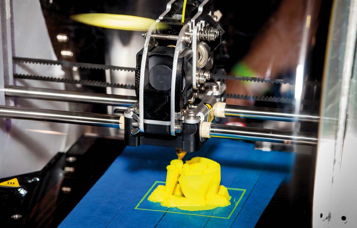
Nowadays, the use of 3D printers in homes and small businesses is growing outside of engineers and tinkerers,1 so 3D printers must remain 100% relia-ble with near zero failed prints due to mechanical and electro-mechanical malfunctions. One of the most impor-tant leading causes of print failure is filament feeding mechanism. Some re-searches and engineers have optimized the grip force on 3D printer filament and even have developed novel feeding mechanisms without filament.2,3
Extrusion failures in FDM 3D printers include those related to the extruder, hot end and filament. The main extrusion problem that occurs to FDM 3D printers arises when the filament does not move as it is desired, which produces jams in extruder or in extruder drive pulley. This problem may be due to damage, stress, dust and small debris in filament. Nevertheless, the most common problems spring from a wrong filament diameter, bra-king of the filament, or simply that the filament coil is over. In these cases, the printer keeps on printing but it does not deposit any material.4,5
Although manufacturers and re-searches are constantly improving polymers manufacturing process, in-cluding fiber spinning and injection molding, the product quality and production efficiency is influenced by multiple processing and material pa-rameters, such as the nominal shear and shear history, process temperature or long chain branching, mechanisms that currently are not completely un-derstood. The control and optimiza-tion of such operations contribute to get closer and closer to the nominal filament size but it still moves in fairly large tolerances.6-9 Moreover, the pos-sibility of continuously checking the deposited filament, allows to reach a better quality of the printed parts.10,11
In this paper, we present a develo-pment to detect the root of the extru-sion failures (may be a knot coil, an extruder jamming or simply the fila-ment coil ends). It is proposed trying to detect that the filament is carried forward properly. To reach this goal, it is initially thought of a mechanical switch that detects when the filament fails to move, but although it seems trivial to cases in which the filament breaks or runs out, it is more difficult to detect the correct advance. For this reason, we propose to use a rotation encoder driven by the movement of the filament. The printer should con-sult repeatedly, while printing, that the encoder is rotating and therefore the filament is going forward. In the event that no progress is detected, the machine will stop and offer the option to download the filament, reload it and continue printing not having to dis-card the part.
review of extruder-filament sensors used for current 3D printers
Mechanical sensor
Mechanical sensors have been widely implemented in 3D printers, the ma-jority of them use a mechanical button to stay on while filament is detected could easily detect filament end or breakage to stop the printing. It is pos-sible to find some detection systems using mechanical filament breakage sensors, but this kind of systems does not solve the main problem, which is a filament jam, as the state of the switch would not change.
Load cell sensor
As the extruder feeds the filament to the hot end, the extruder is effectively pushing against the filament causing the extruder to apply extra load on the load cell. Load cells have strain gauges
attached that change in electrical
resistance when under different loads.
This resistance change provides small
voltage levels that can be amplified
and then read by an analogue to digital
converter.12 Unfortunately, load
cell sensor could make it difficult to
calibrate without a suitable weighing
platform and stand.13
Rotary encoder
A rotary encoder, also called a shaft
encoder, is an electro-mechanical device
that converts the angular position
or motion of a shaft or axle to an
analog or digital code.14 There are two
main types: absolute and incremental
ones. The output of absolute encoders
indicates the current position of the
shaft, making them angle transducers.
The output of incremental encoders
provides information about the motion
of the shaft, which is typically
further processed elsewhere into information
such as speed, distance and
position. Encoder may have mechanical
problems due to the high accuracy
that must be taken to fabricate them.
Environmental pollution can be a
source of interference in optical transmission.
They are particularly sensitive
to shock and vibration devices, and
their operating temperature is limited
by the presence of electronic components.
Mechanical encoder
Mechanical encoders have an axis that
spins internally activating, thus, different
pins depending on the direction
of rotation and speed. Although this
type of encoder firstly seems easy to
use, the resistance of the rotation axis
is considerable, and it is not desired to
increase the resistance of the filament
feed because it could affect the proper
operation of the extruder.
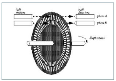
Optical encoder
The principle of operation of an optical
encoder is based on the so-called
photo couplers. These are small chips
consisting of a diode as a photo emitter
and a transistor which performs
the tasks of photoreceptor (see Figure
1). This element is responsible for detecting
the presence/absence of light
through a concentric axis. It is manufactured
with slots that allow the light
to go through the disc to obtain the
final measure.15

Filament auto-detection system development
Election of the sensor
The Weighted Objectives Method is
one of the most common evaluation
methods for comparing design concepts
based on an overall value per design
concept.16 The biggest disadvantage
of using other methods like the
Datum method or the Harris profile is
that the scores per criterion cannot be
aggregated into an overall score of the
design alternative. This makes a direct
comparison of the design alternatives
difficulty. The Weighted Objectives
Method does exactly this: it allows the
scores of all criteria to be summed up
into an overall value per design alternative.
The Weighted Objective Method
assigns scores to the degree to which a
design alternative satisfies a criterion.
However, the criteria used to evaluate
the design alternatives might differ
in their importance. For example,
the cost price can be of less importance
than appealing aesthetics. The
Weighted Objectives Method involves
assigning weights to the different criteria. This allows the decision-maker
to take into account the difference in
importance between criteria.
The selected criteria and compared
in Table 1 are the following:
E1. Filament detection (yes-no)
E2. Detecting the advance of the filament
E3. Not interference with normal movement of the filament
E4. Adaptability of the output signal
E5. Price
E6. Durability
Taking into account the scores (see
Table 2), and as expected, the sensor
that best meets the specifications is
the optical encoder. In this work, an
inexpensive bi-directional optical incremental
encoder is used.
Hardware assembly
Assembly part design
Once the sensor is chosen, it is necessary
to design the part where it will be
installed. It must be taken into account
that it cannot interfere with the normal
function of the machine. To do
it, we will employ photogrammetry
scanning methodology since it will be
possible to do it in a precise way.17 This
method uses reverse engineering thus
allowing to reduce the costs of the development.
After taking numerous pictures of
the object, they are processed using
a computer software so that common
points are identified on each image. A
line of sight (or ray) can be constructed
from the camera location to the point
on the object. It is the intersection of
these rays (triangulation) that/which
determines the three-dimensional location
of the point.
The result of the process is a digital
tridimensional object which can be
used as a model to design the rest of
the parts. It is interesting to include
graphic scales to get the correct dimensions
of the digital model. Figure
2 shows a sample of a total of 74 images
involved in the process.
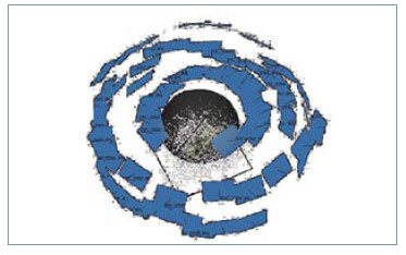
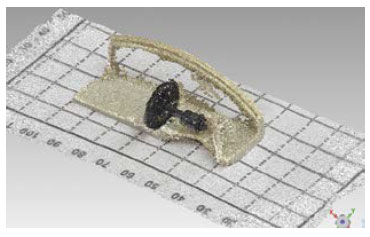

The software locates the pictures
and shapes a points cloud of the scanned
object. The process is showed in
Figure 3 and 4, where it is possible to
see the pictures completely orientated
and the formatted points cloud.
As it is possible to notice in Figure
4, there are some defective parts. This
is due to the brightness of the object,
so it is necessary to perform a repair
of the digital model. Thus, a model as
similar to the real as possible can be
reached. To achieve this, first of all
a filter of the points is performed to
remove the noise eliminating points
spaced of the set a specified size. After
this, different holes are detected. In
this case a total of 698 of holes which
670 are closed automatically since have
a small size. The remaining 28 holes
are manually closed to keep the original
form. An automatic reparation of
errors is carried out, and finally, we get
the digital solid model. Figure 5 shows
an image of the process and the final
model.
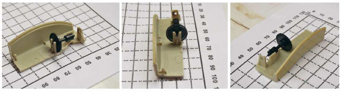
Once the three-dimensional solid model is obtained, it is exported to a 3D design program for modeling the part where it will be assembled. In this way, it is possible to avoid design errors to be made too many times to iterate to find the optimal model. In Figures 6 and 7 the dimensions of the modeled part and the real product made with a 3D printer are showed.
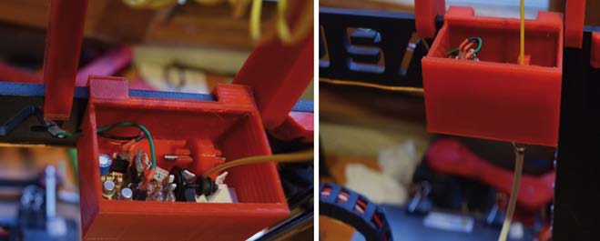
System assembly
The whole system is installed on the top of the printer, so that the filament goes through the sensor. The filament is leaded through a Teflon tube to the hot-end, analogously to Bowden sys-tem.
After checking that the system does not interfere in the normal function of the machine, it is connected to the main electronic board of the printer (an Arduino Mega board). Figure 8 shows the system installed.
Firmware modifications
Once the system is installed, it is ne-cessary to modify the firmware of the machine, so it is possible to get the sen-sor signal and act accordingly. Since the encoder works asynchronously, it is necessary to use program interrup-tions to get the signal correctly. These interruptions will detect whether the filament is moving or is blocked. Mo-reover, it will be possible to calculate the speed at which the filament is ad-vancing in order to be sure about the quantity of material deposited.
However, after repeated tests, it is observed that the interruptions take place very frequently, which interferes with the operation of the printer. That is why we finally choose for attending interruptions every 5 seconds, regard-less when interruptions occurs the rest of the time. After several tests, it is pro-posed that after 10 seconds it will have produced at least one interrupt of the filament if it is proceeding correctly, and otherwise, 10 seconds without de-tecting an interruption should be suffi-cient to stop printing due to an error in filament advancing. A new pause menu is also implemented, since error fila-ment was not previously available.
Once an error in advancing fila-ment is detected, the printer activates the implemented pause mode becau-se of filament error, from which it is possible to load and unload the actual filament to continue printing avoiding to lose the piece.
Results and discussion
Filament defects
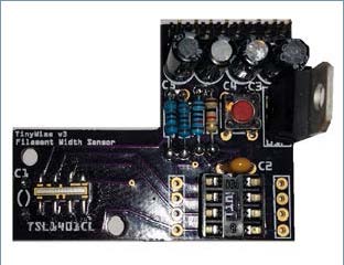
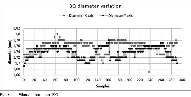
Although most of filament producers for 3D machines are constantly deve-loping and improving their products, the manufacturing method has so far prevented achieving a filament with a constant diameter. This excess in diameter is sometimes too much for the machine, causing bad finishing models, jamming of the extruder, or even it could damage the extruder. To check the filament diameter of diffe-rent producers, 03 meter samples were taken, every centimeter of filament using a sensor with a resolution of – mm.
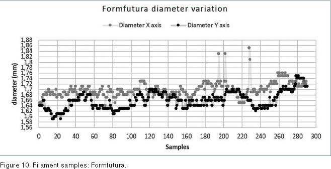
The sensor used is shown in Figure 9, and in Figures 10 to 13 the variation of diameter (whose nominal value is
– mm), in X and Y axis.
By analyzing these samples (see Table 3), it is possible to see that the diameter varies from 1.59 mm to 1.85 mm, with an average of 1.68 mm in one case, and from 1.67 mm to 1.8 mm, with an average of 1.75 mm in the other case. Booth filaments may obs-truct the printer extruder.
Any of these failures makes that after leaving the printer in operation the piece that was being created is lost and it is necessary to start again. In addition, by continuing printing wi-thout really extruded plastic, the ma-chine consumes energy and produces an unnecessary wastage. Due to this reason, the operator must be aware of the machine as long as it is operating, ensuring that the plastic flows without any problem, which is especially diffi-cult when the piece takes several hours to be produced. Moreover, the control of the length of material extruded spe-cially at the perimeters gets an impro-vement of the surface finish.18


Evaluation of the implemented system
The installed system does not affect
the print quality of the machine. It has
been found that the time set for detecting
advancing filament problems
detects an error in time without producing
false positives. In Table 4, the
error is displayed on the printer.
In Figure 14 a piece that was printed
by the filament is showed ended
and continued after detecting another
colour is displayed twice.
As it can be seen, the piece was
completed without any problem and
the adhesion of the three different filaments
was correct.
Conclusions
The installed system achieved perfectly
detects the advance of the filament
without affecting the normal
operation of the machine. The final
frequency to check the advancing filament
(every 5 seconds) allows to detect
any problem with it, and there are no
errors that can appear if the sensor is
checked with a higher frequency. Although
it had been raised as a possible
option to detect the speed, with
the sampling frequency set it is not
possible to calculate it, but meets the
initial objectives of troubleshooting in
advancing filament.
This has made possible the use of
the printer with remains coil filament,
which were not spent because they
were not sufficient to complete an impression.
With this system, when the
filament finishes, the printer enters
into a standby state waiting for the
user to introduce a new filament.
Therefore the primary objective of
the system is achieved, avoiding loss of
material, energy and mechanical wear,
keeping the premise of making a low
cost product that does not significantly
increase the cost of the machine.
References
1. Pearce, J. M., Blair, C. M., Laciak, K. J., Andrews,
R., Nosrat, A. and Zelenika-Zovko, I. 3-D printing
of open source appropriate technologies for selfdirected
sustainable development. Journal of
Sustainable Development, 3(4) (2010), p17.
2. Fiedler, M. Evaluating Tension and Tooth Geometry
to Optimize Grip on 3D Printer Filament. 3D
Printing and Additive Manufacturing, 2(2) (2015),
85-88.
3. Volpato, N., Kretschek, D., Foggiatto, J. A., & da
Silva Cruz, C. G. Experimental analysis of an
extrusion system for additive manufacturing based
on polymer pellets. The International Journal of
Advanced Manufacturing Technology, (2015) 1-13.
4. Bell, C. Common Problems and Solutions.
In Maintaining and Troubleshooting Your 3D Printer.
(2014) 481-487. Apress.
5. Evans, B. Practical 3D printers: The science and art
of 3D printing. (2012) Apress.
6. Volpato, N., Kretschek, D., Foggiatto, J. A., & da
Silva Cruz, C. G. Experimental analysis of an
extrusion system for additive manufacturing based
on polymer pellets. The International Journal of
Advanced Manufacturing Technology, (2015) 1-13.
7. Turner, B. N., and Gold, S. A. A review of melt
extrusion additive manufacturing processes: II.
Materials, dimensional accuracy, and surface
roughness. Rapid Prototyping Journal, 21(3)
(2015), 250-261.
8. Turner, B. N., Strong, R., and Gold, S. A. A review
of melt extrusion additive manufacturing processes:
I. Process design and modeling. Rapid Prototyping
Journal, 20(3) (2014), 192-204.
9. Ratzsch, K. F., Kádár, R., Naue, I. F. and Wilhelm,
M. A Combined NMR Relaxometry and Surface
Instability Detection System for Polymer Melt
Extrusion. Macromolecular Materials and
Engineering, (2013) 298(10), 1124-1132.
10. P. M. Pandey, N.V. Reddy, S.G. Dhande. Real time
adaptive slicing for fused deposition modelling.
International Journal of Machine Tools and
Manufacture, Volume 43, Issue 1, January 2003,
Pages 61–71
11. D. T. Pham, R.S Gault. A comparison of rapid
prototyping technologies. International Journal of
Machine Tools and Manufacture, Volume 38, Issues
10–11, October 1998, Pages 1257-1287
12. Heywood, M. (2013), ”Airtripper Extruder Filament
Force Sensor – Design & 3D Print”, available at
http://airtripper.com/1473/airtripper-extruderfilament-
force-sensor-design-3d-print/ (accessed
2 May 2016).
13. Heywood, M. (2013), ”Electronic Kitchen Scales
Teardown Versus Load Cells” available at http://
airtripper.com/1397/electronic-kitchen-scalesteardown-
versus-load-cells/ (accessed 2 May
2016).
14. Zinniel, R. L., and Batchelder, J. S. (2000). U.S.
Patent No. 6,085,957. Washington,
DC: U.S. Patent and Trademark Office.
15. Nihommori, S., Sakagami, S., and Yaku, T.
(2003). U.S. Patent No. 6,635,863. Washington,
DC: U.S. Patent and Trademark Office.
16. Roozenburg, N. F., and Eekels, J. Product design:
fundamentals and methods (Vol. 2) (1995).
Chichester: Wiley.
17. Egels, Y. and Kasser, M. Digital photogrammetry.
CRC Press. (2003).
18. Pulak M Pandey, N Venkata Reddy, Sanjay G
Dhande. Improvement of surface finish by staircase
machining in fused deposition modeling. Journal
of Materials Processing Technology Volume 132,
Issues 1-3, 10 January 2003, Pages 323-331.