

Effect of the cutting-edge radius on machining processes of the Ti6Al4V alloy
Efecto del redondeo de la arista de corte en procesos de mecanizado de la aleación Ti6Al4V
J. L. Cantero Guisández (1), A. Guerra Sancho (1), A. Sáez Álvarez (1) y M. H. Miguélez Garrido (1)
Nota para el lector/a: algunos símbolos científicos/técnicos podrían no reflejarse de forma correcta en el texto de este artículo, por lo que se recomienda consultarlos en el Documento PDF adjunto más arriba.
Resumen
La microgeometría del filo de las herramientas de corte tiene un efecto determinante en su duración y en la calidad del acabado de la pieza. Actualmente, se están logrando avances significativos en la implementación de técnicas que permiten obtener con elevada precisión redondeos de arista de corte simétricos y asimétricos. Para aprovechar el potencial de estas tecnologías es necesario determinar el efecto de los distintos tipos de redondeo de filo sobre el rendimiento de la herramienta en función de los parámetros de corte y material mecanizado. En este trabajo se han desarrollado modelos numéricos bidimensionales de procesos de mecanizado de la aleación Ti6Al4V considerando distintas preparaciones de filo y parámetros de corte. Estos modelos han sido validados a partir de resultados experimentales obtenidos de referencias científicas internacionales. Los resultados obtenidos confirman la necesidad de emplear elevadas densidades de mallado para poder reproducir el efecto de las distintas preparaciones de filo y la relevancia de establecer redondeos de filo adecuados a cada proceso de mecanizado. El incremento del radio de la arista de corte incrementa la robustez de la herramienta frente a determinados tipos de desgaste como el astillado, pero provoca mayores esfuerzos de corte y temperaturas que aceleran otros mecanismos de desgaste como la abrasión y la difusión. Este efecto es especialmente relevante en los procesos de mecanizado de titanio debido a que este material se vuelve extremadamente reactivo por encima de aproximadamente 600 ºC.
Palabras clave: Análisis numérico, corte ortogonal, mecanizado, Ti6Al4V, Deform 2D.
Abstract
The microgeometry of the edge of cutting tools has a determining effect on both their lifespan and the quality of the workpiece surface finish. Significant advancements are currently being achieved in implementing techniques that allow for obtaining highly precise cutting-edge rounding, both symmetric and asymmetric. To leverage the potential of these technologies, it is necessary to determine the effect of the different types of edge rounding on tool performance as a function of cutting parameters and machined material. In this work, two-dimensional numerical models of Ti6Al4V alloy machining processes have been developed considering different edge preparations and cutting parameters. These models have been validated using experimental results obtained from international scientific references. The results obtained confirm the necessity of using high mesh densities to reproduce the effect of the different edge preparations and the relevance of establishing edge rounding appropriate for each machining process. Increasing the cuttingedge radius enhances the tool’s robustness against certain types of wear, such as chipping. On the other hand, it also causes higher cutting forces and temperatures, which accelerate other wear mechanisms like abrasion or diffusion. This effect is especially relevant in titanium machining processes because this material becomes extremely reactive above approximately 600 ºC.
Keywords: Finite element analysis, orthogonal cutting, machining, Ti6Al4V, Deform 2D.
Recibido/received: 03/07/2025
Aceptado/accepted: 14/10/2025
(1) Departamento de Ingeniería Mecánica, Universidad Carlos III de Madrid.
Corresponding author: J.L Cantero; e-mail: jc******@******3m.es.
1. INTRODUCTION
One of the cutting tool characteristics that most influences the machining process is the cutting-edge microgeometry, which includes different parameters such as edge rounding, chamfering, and edge roughness. This work focuses on the analysis of the influence of edge rounding, considering both symmetric and asymmetric rounding, the latter characterized by having different rounding radii on the flank and rake faces.
Larger edge rounding is related to more robust tools and thus more resistant to wear. However, it must also be considered that variations in the edge geometry affect the material deformation and the heat generation in the cutting zone, leading to different temperature distributions in the material and the tool, as well as different pressure distributions in the tool-surface contact area. These thermomechanical effects significantly impact both the quality of the machined component and the severity of tool wear. Specifically, larger edge rounding is associated with poorer surface finishes on the workpiece and more aggressive conditions in the cutting zone for the tool. Asymmetric rounding can be an interesting option in some applications by allowing the combination of robust edge geometries while maintaining reduced cutting forces and temperatures (Denkena & Biermann, 2014; Wyen & Wegener, 2010; Zhuang et al., 2021).
Numerous studies have shown that an adequate edge preparation can significantly prolong tool life, which contributes to the sustainability of cutting tools. For example, collaborative investigations conducted by CIRP partners evaluated various edge preparation methods in the milling of different materials, such as hardened and stainless steels, Inconel 718, and Ti6Al4V (Bouzakis, et al., 2014). These studies highlight the considerable benefits of edge preparation, especially for difficult-to-machine materials.
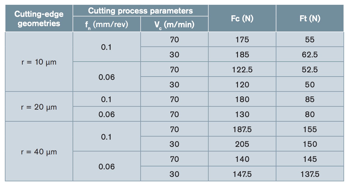
model). Vc: cutting speed; fn: feed rate; Fc: cutting force; Ft: thrust force.
However, the effectiveness of the cutting-edge preparation depends on tailoring the design and process to the specific machining application, workpiece material, and thermomechanical load. The optimal cutting-edge microgeometry is largely determined by the material to be machined and the cutting conditions. Therefore, developing an adequate cutting-edge design requires extensive experimental research to optimize tool performance (Bassett, et al., 2012; Bergmann & Grove, 2018; Mativenga, et al., 2024).
With the aim of reducing the number of experimental campaigns, there are approaches for designing and optimizing the cutting-edge microgeometry based on finite element simulations and statistical models (Biermann, et al., 2018; Li, et al., 2022; Özel & Zeren, 2007; Tiffe, et al., 2019).
In line with this approach, the present work focuses on the development of two-dimensional numerical models of orthogonal cutting machining processes of the Ti6Al4V alloy, considering different edge microgeometries and cutting parameters. These models have been validated using experimental results obtained by C.F. Wyen and K. Wegener (2010) for the orthogonal cutting of Ti6Al4V with rounded cutting edges in the range of 10 to 50 microns in radius, obtained by abrasive micro-blasting.
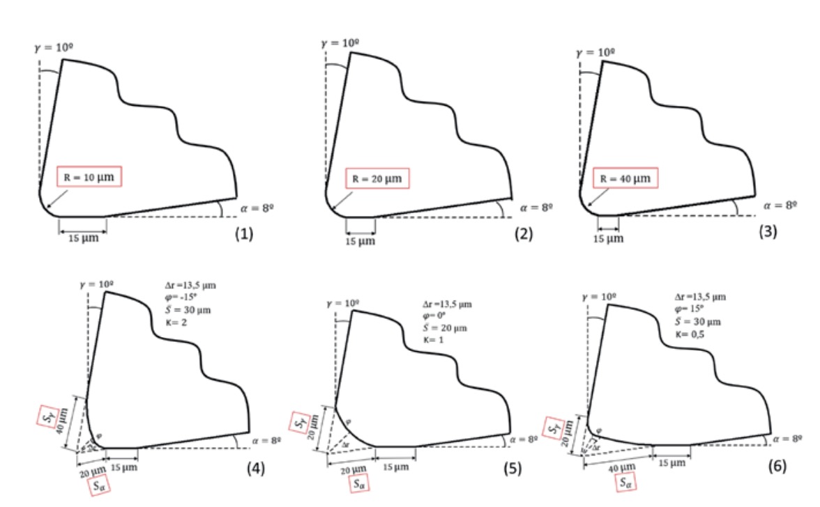
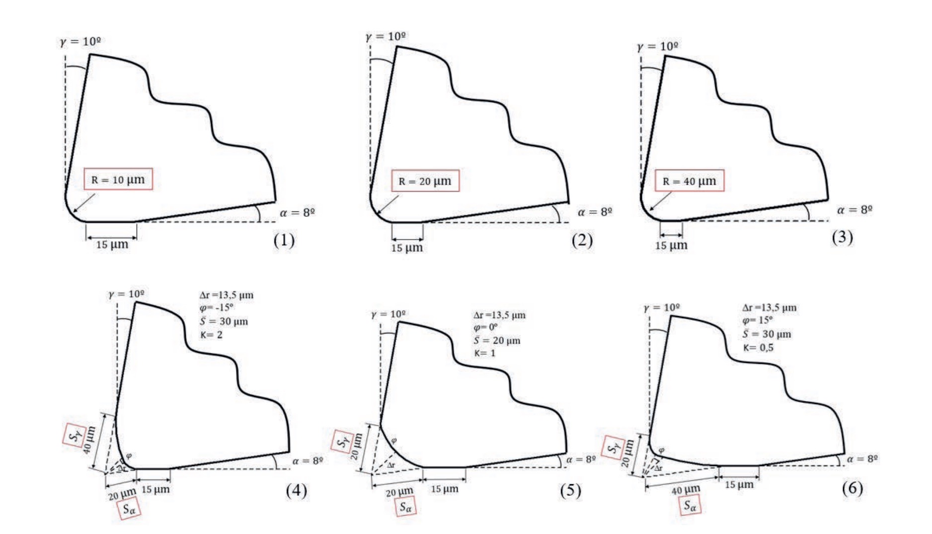
?m (1), 20 ?m (2) and 40 ?m (3); Asymmetrical roundings with parameters S = 20 ?m and S = 40 ?m (4)
and S = 40 ?m and S = 20 ?m (6); Symmetrical roundings with parameters S = 20 ?m and S = 20 ?m (5).
2. METHODOLOGY
For the validation of the developed numerical models, the experimental results shown in the article Influence of Cutting Edge Radius on Cutting Forces in Machining Titanium, by C. F. Wyen and K. Wegener (2010) were used. These tests consisted of turning operations with orthogonal cutting conditions, utilizing soluble cutting fluid cooling, and machining bars of the Ti6Al4V alloy. The magnitudes used for model validation were the components of the cutting forces, which were recorded in the tests using a Kistler 9121 dynamometer. The tools tested were indexable tungsten carbide (WC-Co) insert tools manufactured with a rake angle = 10 º, a clearance angle = 8 º, and different edge preparations.
Table 1 shows the edge geometries, cutting parameters, and the corresponding cutting and thrust forces for the tests considered for model validation. As indicated in the table, the microgeometries correspond to symmetric edge rounding with a radius of 10, 20 and 40 ?m. These geometries and parameters were the ones initially modelled numerically to adjust and validate the model. Once the validation was performed, additional simulations were developed with asymmetric edge rounding geometries to determine the effect of these geometries on the main magnitudes involved in machining.
For the analysis of the numerical simulations, the variables most related to tool wear and thermomechanical damage in the machined component were considered:
•Components of the cutting forces (cutting [Fc] and thrust [Ft] force).
•Maximum temperature on the cutting zone.
•Pressure on the cutting tool.
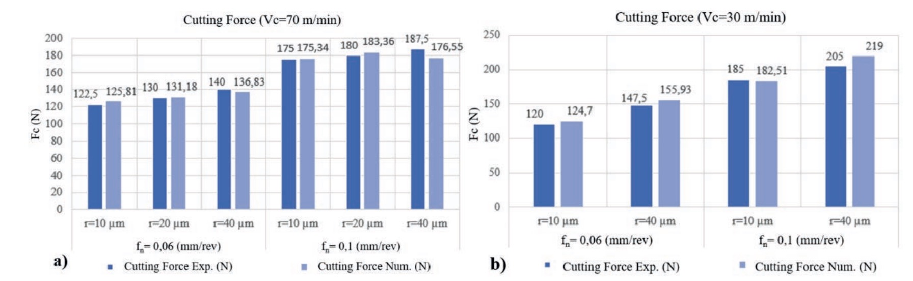
min; b) Cutting force for cutting speed Vc = 30 m/min.
3. DEFINITION AND VALIDATION OF THE NUMERIC MODEL
3.1. Definition of the numeric model
A two-dimensional numerical model corresponding to the machining of the Ti6Al4V alloy has been developed considering plane strain conditions. This type of modelling is an adequate approximation for modelling orthogonal cutting processes where the ratio between the depth of cut and the undeformed chip thickness is at least equal to 12. The model was defined in the DEFORM 2D programming environment based on a Lagrangian formulation with automatic remeshing, making it highly suitable for simulating processes involving large plastic deformations.
Workpiece definition: material, geometry, and mesh:
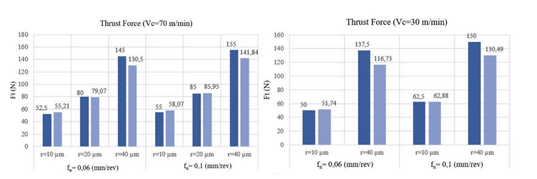
b) Thrust force for cutting speed Vc = 30 m/min.
For the characterization of the workpiece material, information available in the DEFORM library for Ti6Al4V was used, which establishes the relationship between the main thermomechanical variables (stress, strain, strain rate, and temperature) through numerical values ordered in tables. Other material properties relevant for the simulations, such as the coefficient of thermal expansion, thermal conductivity, and specific heat for different temperatures, are also defined in the library. An elastoplastic material behaviour is established. Therefore, the material characterization used is representative of the Ti6Al4V alloy behaviour, but it is not possible to verify its suitability for the specific properties of the material bars used in the validation tests, as this information is not included in the article from which the experimental values are extracted (Wyen & Wegener, 2010).
The workpiece geometry in the model is rectangular, long (in the direction of the cutting motion), and high (corresponding to the direction of the undeformed chip thickness).
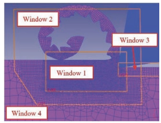
For the workpiece meshing, isoparametric rectangular elements with four nodes were employed. Through a sensitivity mesh analysis, an adaptive meshing of the workpiece with four meshing zones of different densities was established as optimal (Fig. 1). In the chip formation zone (referred to as window 1 in figure 1), the highest mesh density was set, with element sizes of 5 ?m. The rest of the formed chip was meshed with 10 ?m elements of 10 ?m (window 2), with a sufficient density to allow analysis of the chip morphology. The machined surface was also meshed with a relatively high density, using 15 ?m elements (window 3) to allow analysis of temperatures and residual stresses due to machining. Finally, a coarser mesh was used for the rest of the material with an element size of 50 ?m (window 4). A total of approximately 10,000 elements were necessary for the material meshing.
Tool definition: material, geometry, and mesh:
Similar to the workpiece material, the information available in the DEFORM library was used for the characterization of the tool material, in this case, the one corresponding to the cutting material known as hard metal, consisting of tungsten carbide with cobalt as a binder (WC-Co). A rigid behaviour was established for the tool because its deformations are insignificant and do not significantly affect the simulation results.
Figure 2 shows the six modelled cutting-edge geometries: four with symmetric rounding and two with asymmetric rounding. Of the four symmetric rounding geometries, the first three are established with cutting edge radii of 10, 20, and 40 ?m. The last symmetric geometry is defined using the geometric parameters and , which are commonly used to define asymmetric rounding. For this last symmetric geometry, a value of 20 ?m was set for both parameters ( and ), which corresponds to a cutting-edge radius of 16.91 ?m. Finally, the two asymmetric rounding modelled correspond respectively to the values and .
Furthermore, as also reflected in figure 2, a flank wear of 15 ?m was added to the edge geometries, which corresponds to the wear that occurs in the first moments of machining, as reported by various authors. This initial wear is commonly referred to as edge stabilization or tool seating, and its value was adjusted to minimize the error of the numerical models.
For the tool meshing, elements similar to those used for the workpiece meshing were employed. An adaptive mesh was defined using two windows: one with a dense mesh affecting the entire contact area of the tool with the chip and the machined surface, with an element size of 5 ?m, and another window encompassing the rest of the tool with an element size of 50 ?m. The total number of elements used for the tool mesh was 1,800 for all geometries.
Boundary conditions, tool-workpiece contact properties, and simulation conditions:
In the model, the cutting movement was established to be performed by the workpiece in the horizontal direction (X-axis), with its movement fixed in the Y-axis (except for the material forming the chip). The boundary conditions established for the tool consisted of preventing its movement in both directions.
The heat transfer coefficient to the environment was set at 200 N/(s·mm·ºC) and the ambient temperature at 20 ºC. However, these values are not very relevant since a specific sensitivity mesh analysis showed that, due to the extremely short simulation times (a few milliseconds), the effect of heat transfer to the environment is negligible.
The tool-material heat transfer coefficient was established at 45 N/(s·mm·ºC), and the distribution of the heat generated at the interface was set at 50 % for the workpiece and 50 % for the tool.
For the material-tool contact, two friction laws were established depending on the zone considered. In the zone corresponding to the cutting edge and the rake face up to a point aligned with the undeformed chip thickness, an adhesion contact law with a shear factor m = 1 was considered. On the rest of the surfaces, Coulomb friction type contact conditions with a coefficient ? = 0.5 were established. These conditions were defined based on the consulted scientific literature.
In relation to the simulation conditions, a 2 ?m feed per step was defined, which is suitable for the size of the elements used for meshing the chip formation zone.
3.2. Validation of the numeric model
As indicated in section 2, the validation of the numerical model was performed using the forces values experimentally obtained under the 10 conditions defined in Table 1. Figure 3 and figure 4 show the corresponding experimental and numerical cutting and thrust force values, generally showing a good correlation. The relative prediction errors for the cutting force have an average value of 3.17 %, and those for the thrust force have an average value of 6.37 %. The maximum error reached was 15.11 % and occurred for the test with the tool having the largest rounding radius (40 ?m) and the lowest cutting speed and feed rate (30 m/min and 0.06 mm/rev, respectively). These errors are reasonable for numerical models of machining processes.
4. RESULTS
The main results obtained from the developed numerical models are shown below.
4.1. Cutting forces components
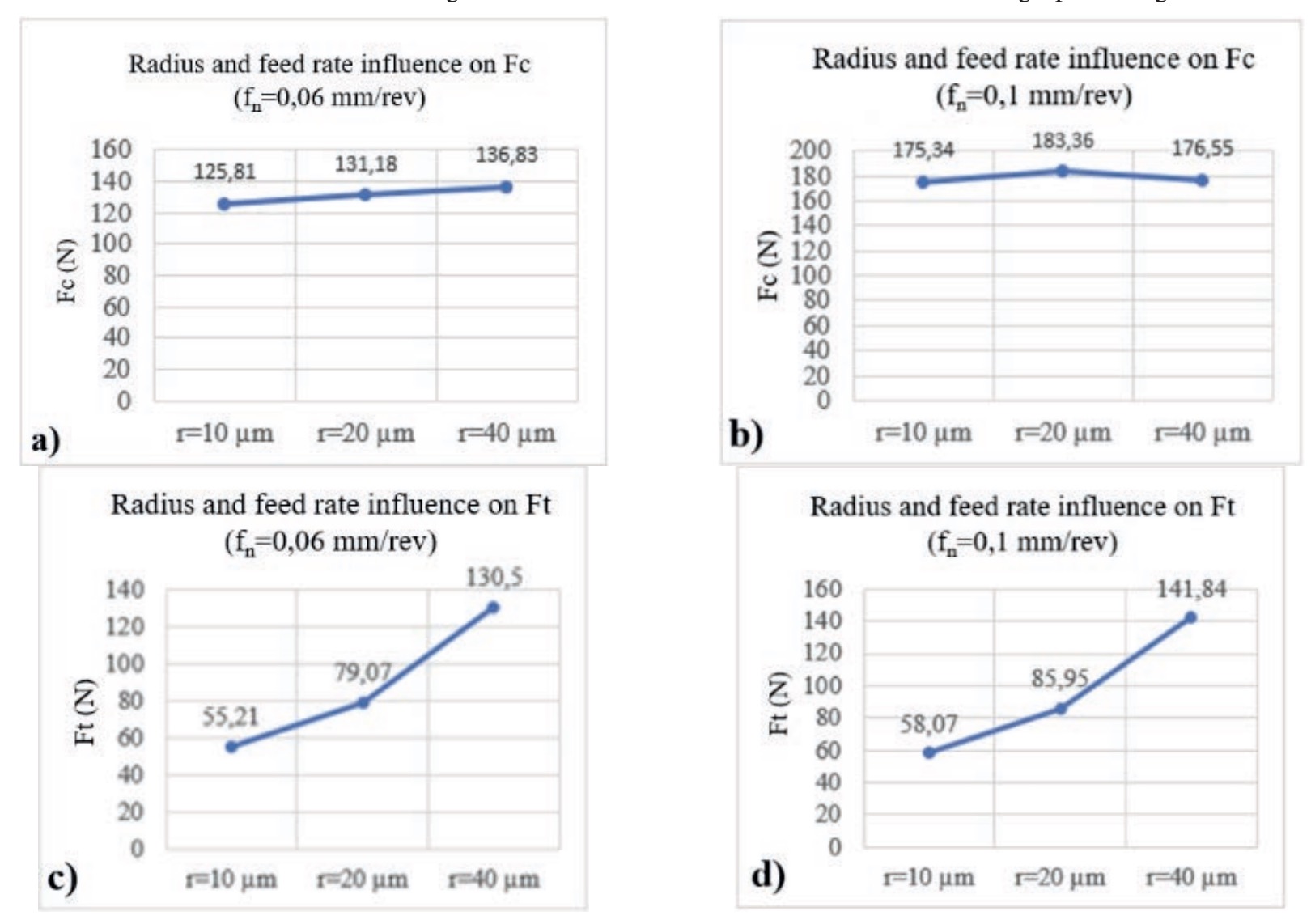
The graphs in figure 5 show the effect of the edge radius and feed rate for three of the symmetric edge rounding geometries.
The effect of increasing the edge radius results in a high rise in thrust force due to the ploughing force caused by the elastic recovery of the material on the tool’s flank face. Specifically, the thrust force for the largest rounding is 2.4 times higher than the thrust force obtained with the tool of the smallest rounding. The cutting force is much less affected by the edge rounding radius.
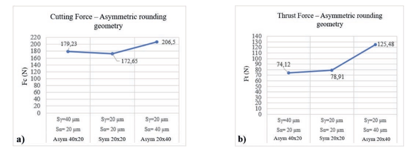
The graphs in figure 6 show analogous information, but for the two asymmetric edge rounding geometries and for the symmetric rounding geometry of the same value.
The most notable trend observed is that the asymmetric rounded tool exhibits thrust and cutting forces very similar to the symmetric rounded tool . However, for the asymmetric tool geometry , the thrust forces obtained are a 60 % higher and the cutting forces are 18 % greater. This result confirms the advantage of using tools with asymmetric edge rounding (in this case with geometries that satisfy ) because they allow for the combination of moderate cutting forces with increased edge robustness.
4.2. Maximum temperature in the cutting zone
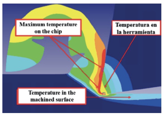
Due to the numerical simulations corresponding to extremely short cutting times (a few milliseconds), the temperature in the tool does not stabilize, reaching values much lower than those typical of titanium alloy machining. Therefore, the maximum temperatures in the cutting zone occur in the chip, specifically in the chip-tool contact area (Fig. 7).
Figure 7. Temperature distribution in the cutting zone corresponding to the model with symmetric rounding of radius = 10 ?m, Vc = 70 m/min and fn = 0.1 mm/rev.
Figure 8 shows the maximum temperatures reached in the cutting zone for different simulations performed with tools with symmetric rounding and with tools with asymmetric rounding.
For tools with symmetric rounding edges (Fig. 8a), it is observed that increasing the cutting speed from 30 m/ min to 70 m/min results in maximum temperatures in the cutting zone that are up to 20 % higher. The increase in feed rate leads to much smaller temperature increases (a maximum increase of 5 %). Larger edge rounding radius cause increases in the maximum temperature of up to 16 %.
Regarding the effect of using asymmetric rounding, figure 8b shows as an example, for the simulations with a cutting speed of 70 m/min and a feed rate of 0.1 mm/rev, the maximum temperatures for the three edge geometries considered, with no significant effect being observed.
4.3. Pressure on the cutting tool
Finally, the pressure exerted by the material on the tool, perpendicular to its profile, and distributed between the rake face and the flank face, is analysed. This magnitude is highly relevant due to its important effect on tool wear.
The behaviour is similar for the different cutting parameters considered, so the results corresponding to the simulations performed with Vc = 70 m/ min and fn = 0.1 mm/rev are shown as an example.
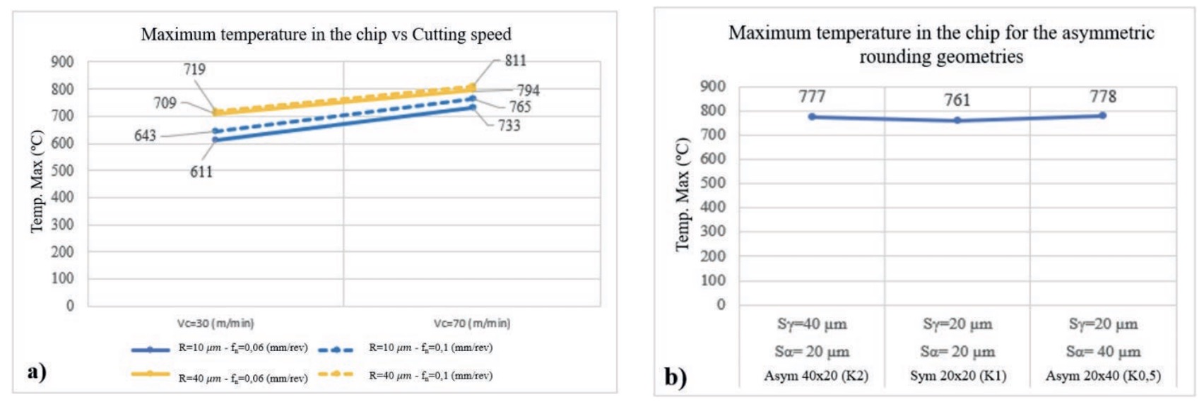
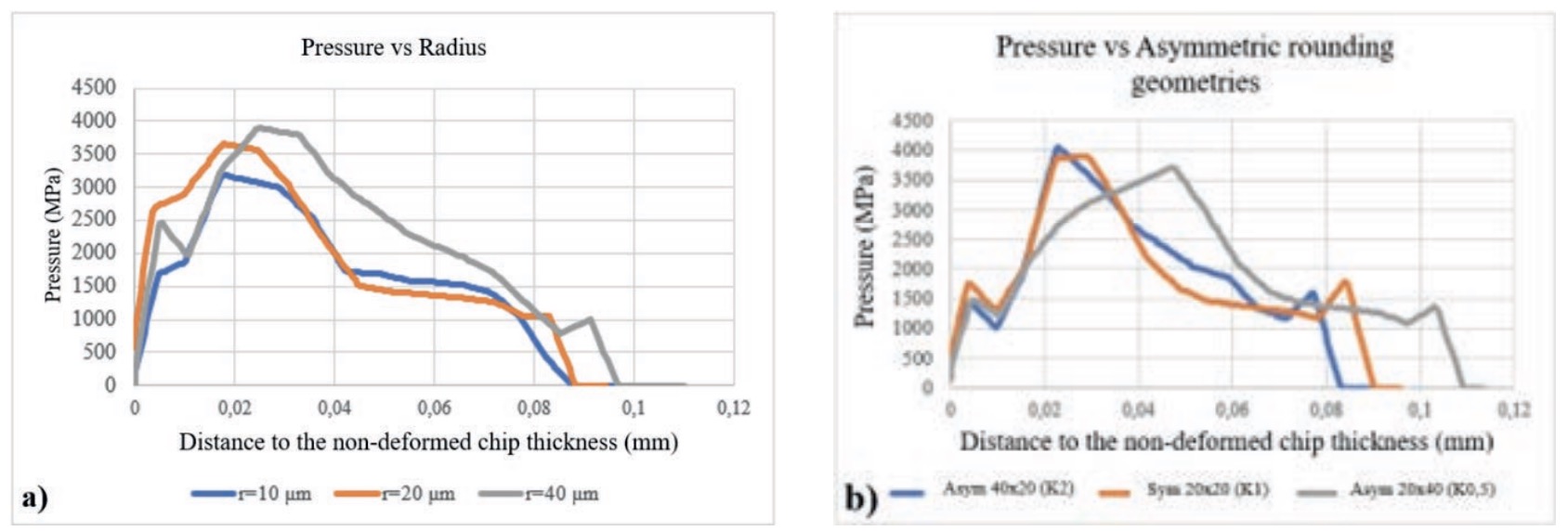
Figure 9 shows how the pressure on the tool varies as a function of the distance to the point where the tool loses contact with the machined surface, for the different edge geometries considered. Figure 9. Normal pressure distribution as a function of the distance to the end of the machined surface-tool contact; a) for tools with symmetric rounding and b) for tools with asymmetric rounding.
For tools with symmetric rounded edges (Fig. 9a), it is observed that the increase in the edge radius causes a small increase in the tool-material contact length and a significant increase in the maximum pressure value of up to 25 %.
Tools with asymmetric rounding (Fig. 9a) show less significant variations in the maximum pressure, being 9 % lower for the S = 40 ?m and S = 20 ?m geometry. Nevertheless, this geometry presents a tool-material contact length almost 30 % greater than the one observed for the simulation with the S = 20 ?m and S = 40 ?m geometry.
5. CONCLUSION
The main conclusions that can be drawn from the described work are the following:
•A two-dimensional numerical model corresponding to the machining of the Ti6Al4V alloy has been developed, considering different cutting-edge geometries with symmetric and asymmetric rounding. The experimental validation carried out generally indicates a good correlation, with average errors obtained for the cutting force of 3.16 % and for the thrust force of 6.37 %.
•The analysis of the machining forces confirms the value of using tools with asymmetric edge rounding, as appropriate configurations exhibit moderate machining forces combined with greater edge robustness.
•For tools with symmetric rounding, the maximum temperature in the cutting zone increases significantly as the edge radius increases. However, using asymmetric rounding does not have a relevant effect on this temperature.
•For tools with symmetric rounding, the maximum normal pressure exerted by the material on the tool increases by up to 25 % when the rounding radius is increased from 10 to 40 ?m. Tools with asymmetric rounding show less significant variations in the maximum pressure, but significant changes are observed in the tool-material contact length.
ACKNOWLEGMENT
The authors acknowledge the help and financial support of the State Research Agency (Agencia Estatal de Investigación) through Project PID2023- 151610OB-C21 funded by MICIU/ AEI/10.13039/501100011033 and FEDER/UE. Los autores agradecen la ayuda y el soporte financiero de la Agencia Estatal de Investigación a través del Proyecto PID2023-151610OB-C21 financiado por MICIU/AEI/ 10.13039/501100011033 and FEDER/ UE.
REFERENCES
Bassett, E., Köhler, J. & Denkena, B. (2012). On the honed cutting edge and its side effects during orthogonal turning operations of AISI1045 with coated WC-Co inserts. CIRP Journal of Manufacturing Science and Technology, 5(2), 108-126. https://doi.org/10.1016/j. cirpj.2012.03.004
Bergmann, B. & Grove, T. (2018). Basic principles for the design of cutting edge roundings. CIRP Annals, 67(1), 73–78. https://doi. org/10.1016/j.cirp.2018.04.019
Biermann, D., Amuth, R., Hess, S. & Tiffe, M. (2018). Simulation based analysis and optimisation of the cutting edge micro shape for machining of nickel-base alloys. Procedia CIRP, 67, 284–289. https://doi. org/10.1016/j.procir.2017.12.214
Bouzakis, K. D., Bouzakis, E., Kombogiannis, S., Makrimallakis, S., Skordaris, G., Michailidis, N., et al. (2014). Effect of cutting edge preparation of coated tools on their performance in milling various materials. CIRP Journal of Manufacturing Science and Technology, 7(3), 264–273. https://doi. org/10.1016/j.cirpj.2014.05.003
Denkena, B. & Biermann, D. (2014). Cutting edge geometries. CIRP Annals, 63(2), 631-653. https://doi. org/10.1016/j.cirp.2014.05.009
Li, B., Zhang, S., Du, J. & Sun, Y. (2022). State-of-the-art in cutting performance and surface integrity considering tool edge micro-geometry in metal cutting process. Journal of Manufacturing Processes, 77, 380-411. https://doi.org/10.1016/j.jmapro.2022.03.037
Mativenga, P., Schoop, J., Jawahir, I. S., Biermann, D., Kipp, M., Kilic, Z. M., et al. (2024). Engineered design of cutting tool material, geometry, and coating for optimal performance and customized applications: A review. CIRP Journal of Manufacturing Science and Technology, 52, 212-228. https:// doi.org/10.1016/j.cirpj.2024.06.001
Özel, T. & Zeren, E. (2007). Finite element modeling the influence of edge roundness on the stress and temperature fields induced by high-speed machining. International Journal of Advanced Manufacturing Technology, 35(3-4), 255-267. https://doi.org/10.1007/s00170- 006-0720-2
Tiffe, M., Aßmuth, R., Saelzer, J. & Biermann, D. (2019). Investigation on cutting edge preparation and FEM assisted optimization of the cutting-edge micro shape for machining of nickel-base alloy. Production Engineering, 13(3-4), 459-467. https://doi.org/10.1007/ s11740-019-00900-8
Wyen, C. F. & Wegener, K. (2010). Influence of cutting-edge radius on cutting forces in machining titanium. CIRP Annals – Manufacturing Technology, 59(1), 93-96. https://doi.org/10.1016/j. cirp.2010.03.056
Zhuang, K., Fu, C., Weng, J. & Hu, C. (2021). Cutting edge microgeometries in metal cutting: a review. The International Journal of Advanced Manufacturing Technology, 116(7-8), 2045-2092. https://doi.org/10.1007/s00170-021- 07558-6.