Deceleration variability of a progressive action safety gear in an inclined elevator
Variabilidad de la deceleración de un paracaídas de acción progresiva en un ascensor inclinado
Beatriz Valles Fernández (1), Enrique Alcalá Fazio (1), Ángel Martín López (1), David Rincón-Dávila (1) y Joel Valenzuela Cuartero (1)
Resumen
Los ascensores inclinados son un tipo de ascensor que se mueven siguiendo la inclinación del terreno. El uso de este tipo de ascensores es muy diverso, ya que puede ser utilizado en centros comerciales, metros, estaciones y aeropuertos, así como en zonas residenciales y en lugares o zonas turísticas con cierto desnivel. Esta opción se ha convertido en una excelente alternativa a las escaleras mecánicas tradicionales al poder ser utilizada para el transporte de personas con discapacidad o personas con movilidad reducida. También presenta una ventaja competitiva frente a las escaleras mecánicas al poder adaptarse a trayectos largos con mayor facilidad. Este tipo de ascensores cuenta con una cabina, habitualmente acristalada, que permite que los pasajeros estén siempre en posición vertical, aunque la trayectoria del terrero sea inclinada. En el caso de los ascensores con trayectoria inclinada, la norma de referencia UNE EN 81:22-2022 establece dos límites de aceleración en caso de actuación del sistema de parada de emergencia: un límite de aceleración horizontal máximo, establecido para evitar que los pasajeros colisionen con las paredes del carro, y un límite de aceleración vertical mínimo que garantiza que el paracaídas tiene una capacidad de frenado suficiente para decelerar el carro en condiciones seguras para los ocupantes en caso de plena carga. En este artículo se presenta el análisis realizado para determinar la viabilidad de uso de un paracaídas de acción progresiva, que forma parte del sistema de seguridad pasiva junto con el limitador de velocidad en los ascensores verticales, como sistema de frenado en caso de emergencia para los ascensores con trayectoria inclinada.
Palabras clave: Modelo de ascensor, ascensor inclinado, paracaídas, amortiguador hidráulico, tope de ascensor, EN 81-22:2020.
Abstract
Inclined elevators are a type of elevator that moves along the incline of the ground. These types of elevators are widely used, and can be used in shopping malls, subways, stations, and airports, as well as in residential areas or places with a certain level difference. This option has become an excellent alternative to traditional escalators, allowing them to be used for transporting disabled or people with reduced mobility. Furthermore, they feature a cabin, usually enclosed in glass, that allows passengers to remain upright, even when the ground is inclined. For elevators with inclined trajectories, the UNE EN 81:22- 2022 standard establishes two acceleration limits in the event of the emergency stop system being activated: a maximum horizontal acceleration limit, established to prevent passengers from colliding with the carriage walls; and a minimum vertical acceleration limit, which guarantees that the safety gear has sufficient braking capacity to decelerate the carriage under safe conditions for occupants if fully loaded. This article presents the analysis conducted to determine the feasibility of using a progressive-action safety gear, which is part of the passive safety system along with the speed limiter in vertical elevators, as an emergency braking system for elevators with inclined trajectories.
Keywords: Hydrogen, thermochemical cycles, perovskites, nuclear energy, and generation IV reactors.
Recibido/received: 03/07/2025
Aceptado/accepted: 13/10/2025
(1) Francisco Aparicio Izquierdo University Institute of Automotive Research, Polytechnic University of Madrid.
Autores para correspondencia: b.******@*pm.es, en************@*pm.es, an**********@*pm.es, da***********@*pm.es y jo*************@*pm.es
1. INTRODUCTION
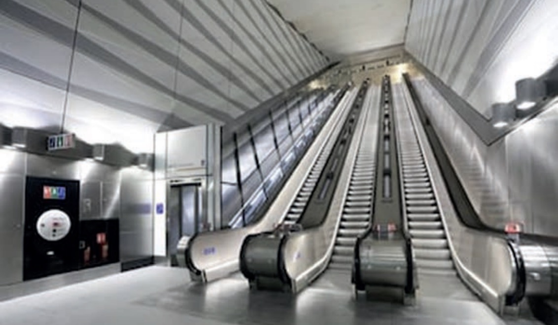
Elevators are a mass transit service that moves hundreds of millions of people every day. Only in Spain, elevators make approximately 48 million trips every day and transport 9.5 million people. This is due to the low probability of serious injury in most incidents (Fig. q). However, it is a means of transportation in which various organizations continue to work to improve its already high safety standards.
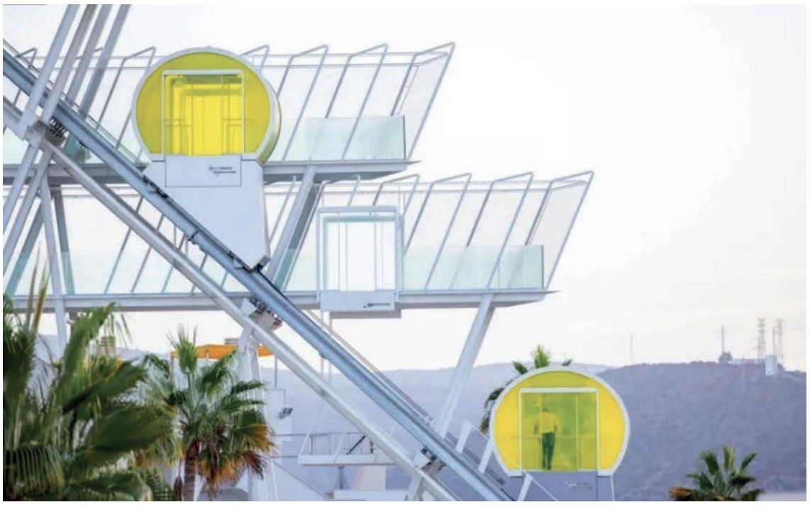
Inclined elevators are a type of elevator that moves along the incline of the ground. These types of elevators are widely used, and can be used in shopping malls, subways, stations, and airports, as well as in residential areas or tourist locations with a certain gradient. This option has become an excellent alternative to traditional escalators, as it can be used to transport people with disabilities or people with reduced mobility. They also offer a competitive advantage over escalators, as they can more easily adapt to long distances. This type of elevator features a cabin, usually enclosed in glass, that allows passengers to remain upright, even when the ground is inclined (Fig. 2).
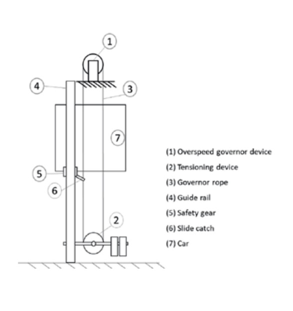
Elevators are a very sensitive element in terms of safety, since a malfunction can cause serious injuries to users and even death. This is why they have a passive safety system installed (speed limiter and progressive or instantaneous safety gear) that comes into operation when the cabin overspeeds or the cables break, causing the cabin to descend in free fall (Fig. 3).
The safety gears (5) are basically made up of a casing that is fixed to the cabin frame (7) (or the counterweight depending on the design), a mobile element -wedge or rollermechanically linked (6) to the wheelhouse whose guided movement causes emergency braking by contact or wedging against the guides (4).
In the case of instantaneous safety gears, very high decelerations occur during braking, while in progressive safety gears there is an elastic element that limits the deceleration in the cabin to 0.6 g. The UNE EN 81:20:2020 and UNE EN 81-50:2020 standards define, respectively, the safety rules for their construction and installation, as well as the inspections and tests that they must comply with in order to be approved. In the case of elevators with an inclined trajectory, the type of safety gear used must have a special configuration, since, while ensuring a minimum level of vertical deceleration, the car will experience a certain level of horizontal deceleration. Therefore, this type of elevator requires different requirements than vertical elevators and is evaluated according to the requirements defined in the UNE EN 81-22:2022 standard. The standard establishes two acceleration limits in the event of the emergency stop system being activated: a maximum horizontal acceleration limit, established to prevent passengers from colliding with the walls of the carriage; and a minimum vertical acceleration limit that guarantees that the safety gear has sufficient braking capacity to decelerate the carriage under safe conditions for occupants if fully loaded. Therefore, the inclination angle causes longitudinal accelerations/decelerations that differentiate the dynamics of both types of elevators (vertical and inclined). In section 5.6.8.4 of the UNE EN 81-22:2022 standard, the deceleration limits established at the moment of the safety gear action with nominal load are indicated: (1) (2)
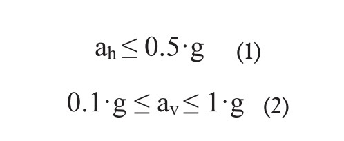 Where ah is the measure of horizontal acceleration and av is the measure of vertical acceleration.
In the case of vertical elevators, the UNE EN 81-50:2020 standard imposes a minimum deceleration of approximately 0.6 g, a deceleration value used to determine the maximum loaded weight that a given safety gear can stop. Comparing the requirements of both regulations, it is worth noting that, for inclined elevators, although the minimum required deceleration is lower, two upper limits are imposed for both vertical (1 g) and horizontal (0.5 g) deceleration. The limits imposed on inclined elevators promote safety by reducing the possibility of passengers colliding with the cabin walls, although they also pose a challenge for the system used in emergency braking, since very specific acceleration levels must be guaranteed.
For manufacturers of elevator safety components, developing an emergency braking system adapted to the requirements of inclined elevators is a handicap. In fact, there is a large amount of literature on the dynamic behaviour of elevators and their components (Pawel, 2017; Pulecchi, 2010; Dapeng, 2022; Tomé, 2022; Xu, 2013, and Wang, 2018), but no literature has been found on the behaviour of the elements used in the emergency braking of elevators with an inclined trajectory.
This article analyses the behaviour of the braking system of an inclined elevator when a progressive safety gear is used as the main element. This would represent a competitive advantage for current manufacturers, since it would allow them to develop new uses for an existing product and enter new markets without increasing production costs.
2. RESULTS
To conduct a feasibility study on a progressive safety gear on an inclined elevator and to determine the variability of its performances a test plan was generated considering the most influential variables for the design of an inclined elevator, such as the type of safety gear, the installation or not of a shock-absorbing element, the angle of inclination of the platform, and the weight of the cabin and passengers.
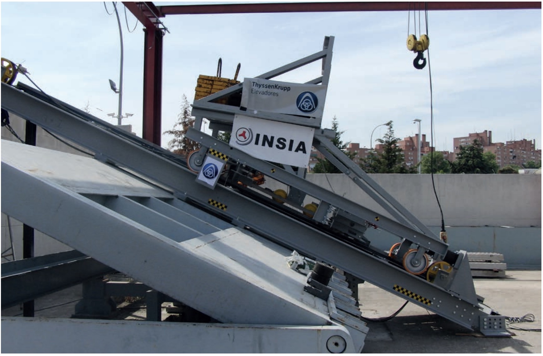
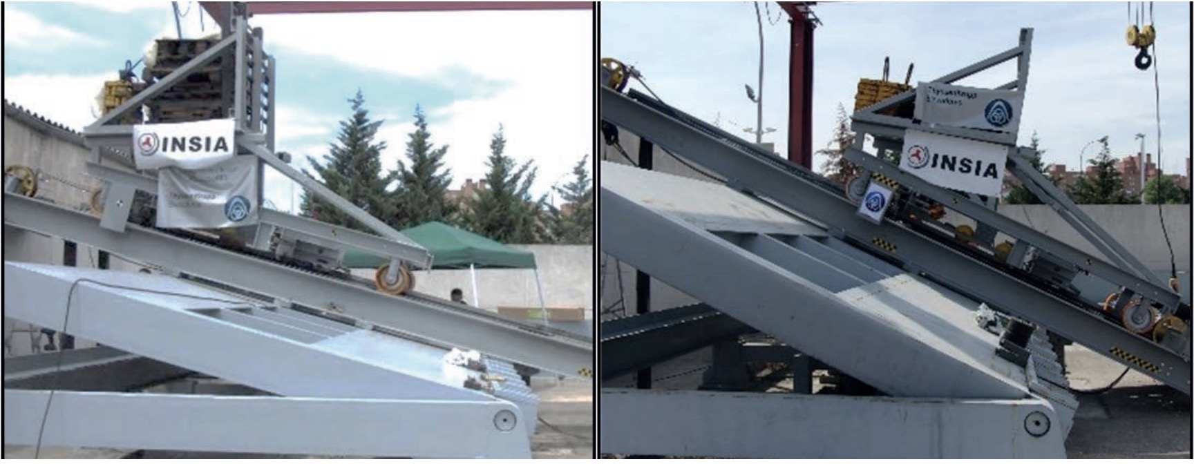
The proposed tests were conducted on the INSIA lateral inclination platform, where the elevator assembly was installed, complete with its rails, guides, safety gear system, and final compression dampers (Fig. 4). The platform’s hydraulic drive made it possible to adjust the elevator’s inclination angle to the established setpoints. The assembly image shows how the trolley’s running rails are mounted on the inclined platform.
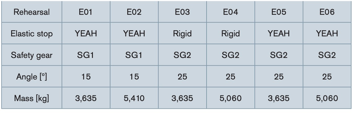
The combination of tests proposed for validation is summarized in table 1. The tests considered two different inclinations: 15 and 25 degrees, with two masses: one corresponding to an empty cabin and the other one corresponding to the maximum load, depending on the inclination and safety gear. A different safety gear was used for each inclination.
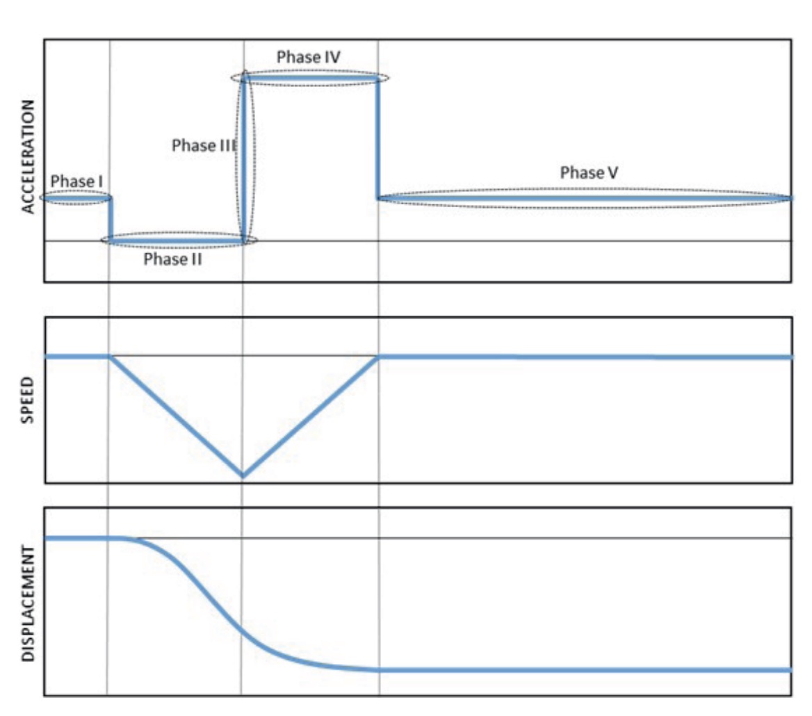
The response of the progressive safety gear, in the case of being installed in an inclined elevator, is similar to that obtained in a vertical elevator (Alcalá, 2012) as can be seen in figure 5 and consists of the following phases:
•Phase I: Initial state, the system is motionless in static equilibrium.
•Phase II: Free fall until the elevator reaches overspeed.
•Phase III: Braking system activation when entering the speed limiter’s operating range.
•Phase IV: Deceleration of the cabin due to the friction force applied by the safety gear against the guide rail. If an additional element is present, it increases the braking distance in this phase.
•Phase V: Final state after the elevator stops.
Currently, manufacturers use hydraulic shock absorbers to meet the regulatory requirements defined in the UNE-EN 81-22:2022 standard, which governs the installation of inclined elevators. Therefore, it was decided to include in the test plan configurations that contemplated both the rigid connection between the safety gear frame and the cabin frame, as well as the use of elastic elements between them.
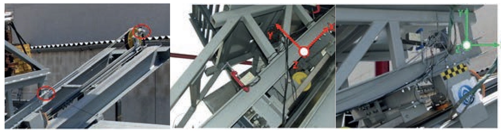
Therefore, six tests were conducted at two different inclinations: 15 and 25 degrees, with two masses: one for the empty cabin and the other for the maximum load, depending on the inclination and safety gear. A different safety gear was used for each inclination. Accelerometers and cable sensors were used to acquire data during the testing process to measure displacements and accelerations in all directions, as illustrated in the following image (Fig. 6).
To assess the feasibility and performance of using progressive safety gears as emergency braking elements for an inclined elevator, a wavelet analysis of the results obtained from the tests was performed to characterize the behaviour of these safety gears when subjected to natural decelerations in an inclined elevator.
Wavelet transform analysis is a tool that allows the analysis of signals in the time and frequency domains; therefore, it has some advantages over the Fourier transform (Pawel, 2017) (Sifuzzaman, 2009) and its modification based on window analysis. This method has been applied in various areas of engineering (Pawel, 2017; Sifuzzaman, 2009), since it is a multiresolution analysis that allows identifying patterns, breakpoints and discontinuities in a signal.
From the acceleration time curve Acc(t) obtained in each of the tests carried out at INSIA facilities, the Continuous Wavelet Transform (CWT) is generated (Kumar, 1997) (Torrence, 1998):
![]() Where represents the function called the mother wavelet or basic function. The parameters and are the means and standard deviations of the acceleration, and the subscripts syn represent the scale and time indices, respectively. The wavelet transform defined by equation (3) is called a continuous wavelet transform (CWT) because the scale and time parameters assume continuous values.
Where represents the function called the mother wavelet or basic function. The parameters and are the means and standard deviations of the acceleration, and the subscripts syn represent the scale and time indices, respectively. The wavelet transform defined by equation (3) is called a continuous wavelet transform (CWT) because the scale and time parameters assume continuous values.
![]() Where is the central frequency or order of the wavelet and the renormalized time variable. To balance the time/frequency resolution, a value is adopted , which defines six oscillations in the complex Morlet-type mother wavelet signal (Pawel, 2017).
Where is the central frequency or order of the wavelet and the renormalized time variable. To balance the time/frequency resolution, a value is adopted , which defines six oscillations in the complex Morlet-type mother wavelet signal (Pawel, 2017).
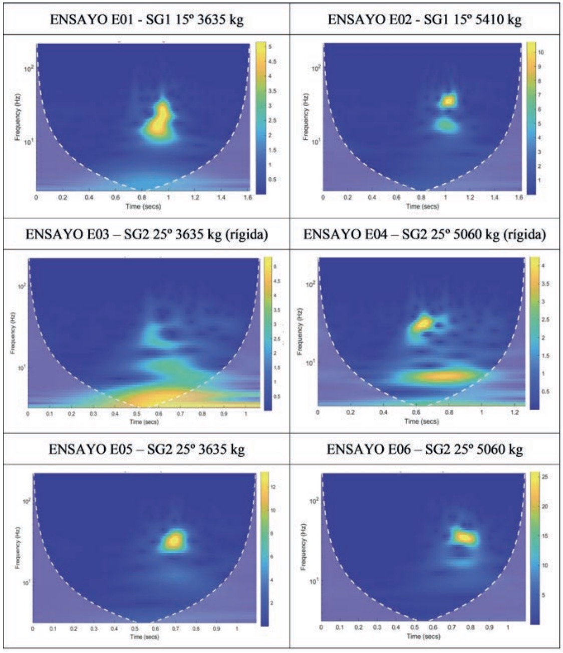
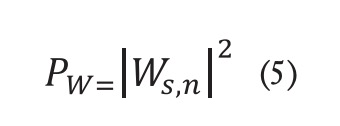
The following figure shows the acceleration signals measured during the test transformed by CWT and presented with the corresponding wavelet power spectrum, PW (11).
 As it can be seen in figure 7, the spectrograms corresponding to the wavelet analysis allow the original signal to be broken down into frequency bands. Furthermore, the colour of each point indicates the magnitude of the signal at each instant and frequency. The area corresponding to high coefficient values appears in yellow, while the blue region is made up of low coefficients. The active braking region can be seen in the power spectra of the acceleration signals, corresponding to the yellow colour. It is significant to observe the change in intensity in the tests corresponding to the removal of the bumper (E03 and E04), since in these cases, the active braking zone of the safety gear is greater in time than in the rest of the tests, where an elastic bumper is used. A detailed examination of the results shows a change in the natural frequency for different angles and for different masses, but it is more evident in the case where the elastic bumper is removed.
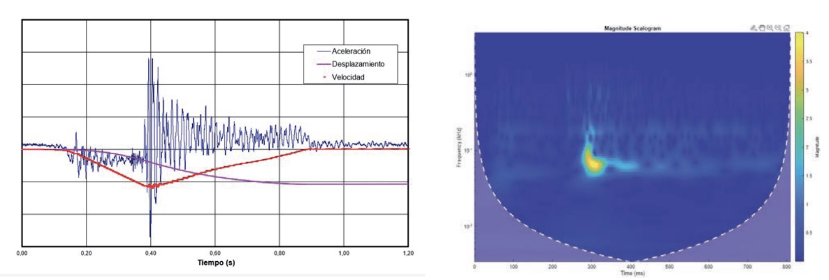
To check whether the active braking region of a progressive safety gear has been modified when installed on an inclined elevator, compared to its original use on a vertical elevator, the spectrogram corresponding to the test curves of these progressive safety gears has been obtained when they were approved according to the UNE EN 81-50:2020 standard (Fig. 8).
As it can be seen, the active braking region that occurs in the safety gear during the vertical test is quite similar to that obtained during the inclined test without the use of additional elements. Furthermore, it is confirmed that the active braking in the vertical test, although very strong at the initial moment, it is maintained over time, which allows compliance with the vertical deceleration requirement established in the reference standard.
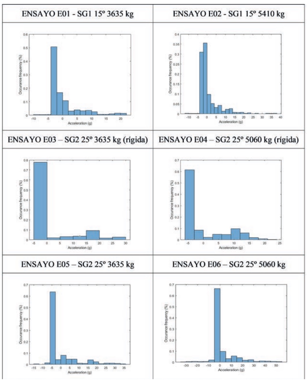
For a more exhaustive analysis, figure 9 shows the histograms corresponding to the signals used for the validation tests carried out. In this case, only the accelerations obtained during the braking of the inclined elevator’s emergency system have been considered for study; the acceleration part has been eliminated to arrive at the speed limiter’s action.
As it can be seen in the histograms corresponding to the cabin acceleration in the direction of travel, in the case of tests at an angle of 25 degrees, peaks of up to 5 g or more are produced, regardless of whether or not a bumper is fitted, while the maximum decelerations measured for an angle of 15 degrees do not exceed 4 g. Asymmetry can also be observed in the graphs due to the peculiarity of the inclined free-fall test, which establishes criteria in both vertical and longitudinal directions. In this case, the resultant of both accelerations, i.e., the acceleration in the direction of travel, is analyzed.
3. CONCLUSIONS
This study has demonstrated the feasibility of installing a progressive safety gear, an element that forms part of the passive safety system of a conventional elevator, as part of the braking system for inclined elevators.
The results obtained allow the manufacturer to turn a handicap into a new market opportunity, since an existing product can be repurposed, and there is no need to invest time and money in developing new solutions that meet the deceleration levels established by inclined elevator regulations.
The developed test plan has confirmed that in order to characterize the behaviour of the progressive safety gear in inclined elevators, it is necessary to evaluate its behaviour in variables as important as the angle of inclination and the weight of the cabin, since in the wavelet analysis performed, the active braking zone of the safety gear can be very different.
The wavelet analysis also reveals that progressive safety gears, when installed on inclined elevators, exhibit different behaviour depending on whether they are connected to the cabin frame rigidly or include an elastic element. If an elastic stop is not installed, the active braking zone of the safety gear is larger, although the maximum deceleration values remain similar.
ACKNOWLEDGMENTS
This work has been made possible thanks to funding from the Segvauto.5G-CM TEC-2024/ECO-277 project, subsidized by the Regional Ministry of Education, Science and Universities of the Community of Madrid, which is part of the 2024 call for R&D projects carried out in collaboration together with research groups from universities and research organizations in the Community of Madrid.
REFERENCES
Alcalá E et al. (2012). “Design of inclined elevators. Development and validation of mathematical models for the design of inclined elevators according to the draft ISO prEN 81-22:2010 standard”. COIIM Journal, No. 56.
Dapeng N et al. (2022). Operation performance evaluation of elevators based on condition monitoring and combination weighting method. Measurement 194, 111091.
Kiymik, MK, Guler I, Dizibuyuk A., Akin M (2004).: Comparison of STFT and wavelet transform methods in determining epileptic seizure activity in EEG signals for real-time applications. Comput. Biol. Med. 35, 603-616.
Kumar P, Foufoula-Georgiou. E (1997). Wavelet analysis for geophysical applications Rev. Geophys., 35, 385-412.
Pawel L et al (2017). Braking deceleration variability of progressive safety gears using statistical and wavelet analyses. Measurement 110, 90-97.
Pulecchi T et al. (2010). Digital filtering of acceleration data acquired during the intervention of a lift safety gears. Measurement 23, 455-468.
Schewer L (2007). Validation metrics for response histories: perspectives and case studies. Windsor; Springer-Velag London Limited.
Shahidul I et al. A wavelet approach for precursor pattern detection in time series. Journal of Electrical Systems and Information Technology 5 (2018) 337-348.
Sifuzzaman, M, Islam MR, Ali MZ (2009). Application of wavelet transform, and its advantages compared to Fourier transform. J. Phys. Sci. 13, 121-134.
Sprague MA, and Geers TL (2004). A spectral-element method for modeling cavitation in transient fluid–structure interaction. Mechanical Engineering, University of Colorado, Boulder, CO 80309-0427, USA Int. J. Numer. Meth. Engg; 60:2467-2499.
Tome M, et al. (2022). Automatic velocity measurement system applied to elevator overspeed governors. Building Services Engineering Research and Technology, 43(5):559-569.
Torrence C, Compo GP (1998). A practical guide to wavelet analysis. Bull. Am. Meteor. Soc., 79, 61-78
UNE EN 81-20:2022 Safety rules for the construction and installation of lifts – Lifts for transport of persons and goods – Part 20: Passenger and goods passenger lifts.
UNE EN 81-50:2022 Safety rules for the construction and installation of lifts – Lifts for transport of persons and goods – Part 50: Design rules, calculations, examinations and tests of lift components.
UNE EN 81-22:2022 Safety rules for the construction and installation of lifts – Lifts for transport of persons and goods – Part 22: Electric lifts with inclined path.
Wang Q., et al (2018). MCU System-based Intelligent High-speed Elevator Door Operator Fault Analysis and Research. IOP Conf. Series: Materials Science and Engineering 428, 012028.
Xu B., et al (2013). Safety brake performance evaluation and optimization of hydraulic lifting systems in case of overspeed dropping. Mechatronics Vol. 23, 1180-1190.